8
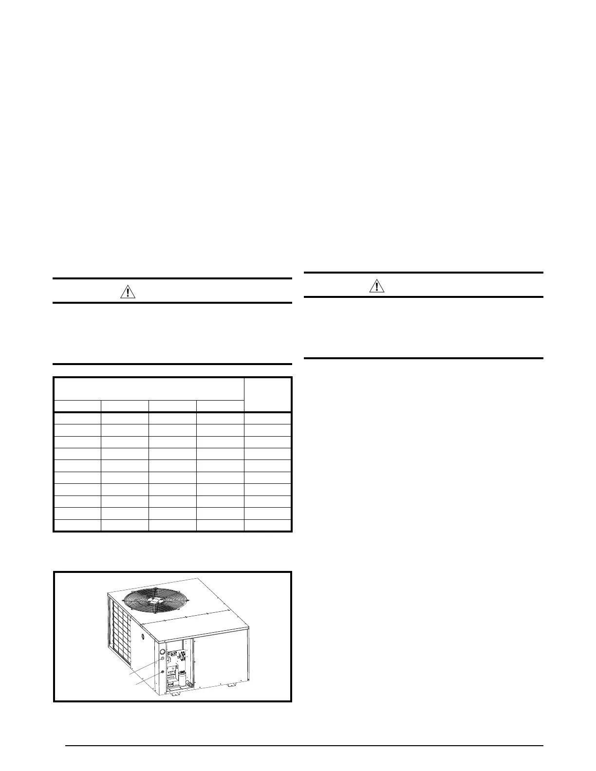
Figure 7. Power Entry
be capable of electrically de-energizing the outdoor unit.
See unit data label for proper incoming field wiring. Any
other wiring methods must be acceptable to authority
having jurisdiction.
• Providepowersupplyfortheunitinaccordancewith
the unit wiring diagram, and the unit rating plate.
• Connecttheline-voltageleadstotheterminalsonthe
contactor inside the control compartment. Extend leads
through power wiring hole (Figure 7). Connect L1 & L2
directly to the contactor.
• Useonlycopperwireforthelinevoltagepowersupply
to this unit as listed in Table 1. Use proper code agency
listed conduit and a conduit connector for connecting
the supply wires to the unit. Use of rain tight conduit is
recommended.
• Seetheunitwiringlabelforproperhighandlowvoltage
wiring. Make all electrical connections in accordance
with all applicable codes and ordinances. See Figures
9 - 11 (pages 20 - 22).
CAUTION:
Label all wires prior to disconnection when
servicing controls. Wiring errors can cause
improper and dangerous operation. Verify
proper operation after servicing.
Overcurrent Protection
Overcurrent protection must be provided at the branch
circuit distribution panel and sized as shown on the unit
rating label and according to applicable local codes.
Generally, the best fuse or breaker for any heat pump
is the smallest size that will permit the equipment to run
under normal usage and provide maximum equipment
protection. Properly sized fuses and breakers also prevent
nuisance trips during unit startup. If a fuse blows or a
breaker trips, always determine the reason. Do not
arbitrarily install a larger fuse or breaker and do not,
in any case, exceed the maximum size listed on the
data label of the unit.
Grounding
WARNING:
The unit cabinet must have an uninterrupted or
unbroken electrical ground to minimize personal
injury if an electrical fault should occur. Do not
use gas piping as an electrical ground!
This unit must be electrically grounded in accordance
with local codes or, in the absence of local codes, with
the National Electrical Code (ANSI/NFPA 70) or the CSA
C22.1 Electrical Code. Use the grounding lug provided in
the control box for grounding the unit.
Supply Wire
Length (Feet)
Supply
Circuit
Ampacity
200 150 100 50
6 8 10 14 15
4 6 8 12 20
4 6 8 10 25
4 4 6 10 30
3 4 6 8 35
3 4 6 8 40
2 3 4 6 45
2 3 4 6 50
2 3 4 6 55
1 2 3 4 60
Wire Size based on N.E.C. for 60° type copper conductors.
Table 1. Copper Wire Size AWG (1% voltage drop)
• Unitsareshippedfromthefactorywiredfor240volt
transformer operation. For 208V operation, remove the
lead from the transformer terminal marked 240V and
connect it to the terminal marked 208V.
Thermostat Connections
• The heat-coolthermostat isequipped witha system
HEAT-COOL switch, which provides a positive means
of preventing simultaneous operation of the heating and
cooling units. The thermostat is also equipped with an
ON-AUTO fan switch which allows the home owner to
operate the indoor blower when air circulation is desired.
• Connectthelowvoltagewirestotherespectiveterminals
on the thermostat base (Figure 12, page 23). See
thermostat instruction sheet for more detailed wiring
information.
• Thethermostatshouldbemountedabout5feetabovethe
floor on an inside wall. DO NOT install the thermostat on
an outside wall or any other location where its operation
may be adversely affected by radiant heat from fireplaces,
sunlight, or lighting fixtures, and convective heat from
warm air registers or electrical appliances. Refer to the
thermostat manufacturer’s instruction sheet for detailed
mounting information.
Defrost Cycle Control
The defrost cycle is initiated via a signal from the defrost
sensor on the outdoor coil to the defrost control board inside
the control panel. This indicates the coil temperature is low
enough to start accumulating frost. The board has interval
settings of 30, 60, and 90 minutes. These time intervals
 Loading...