6
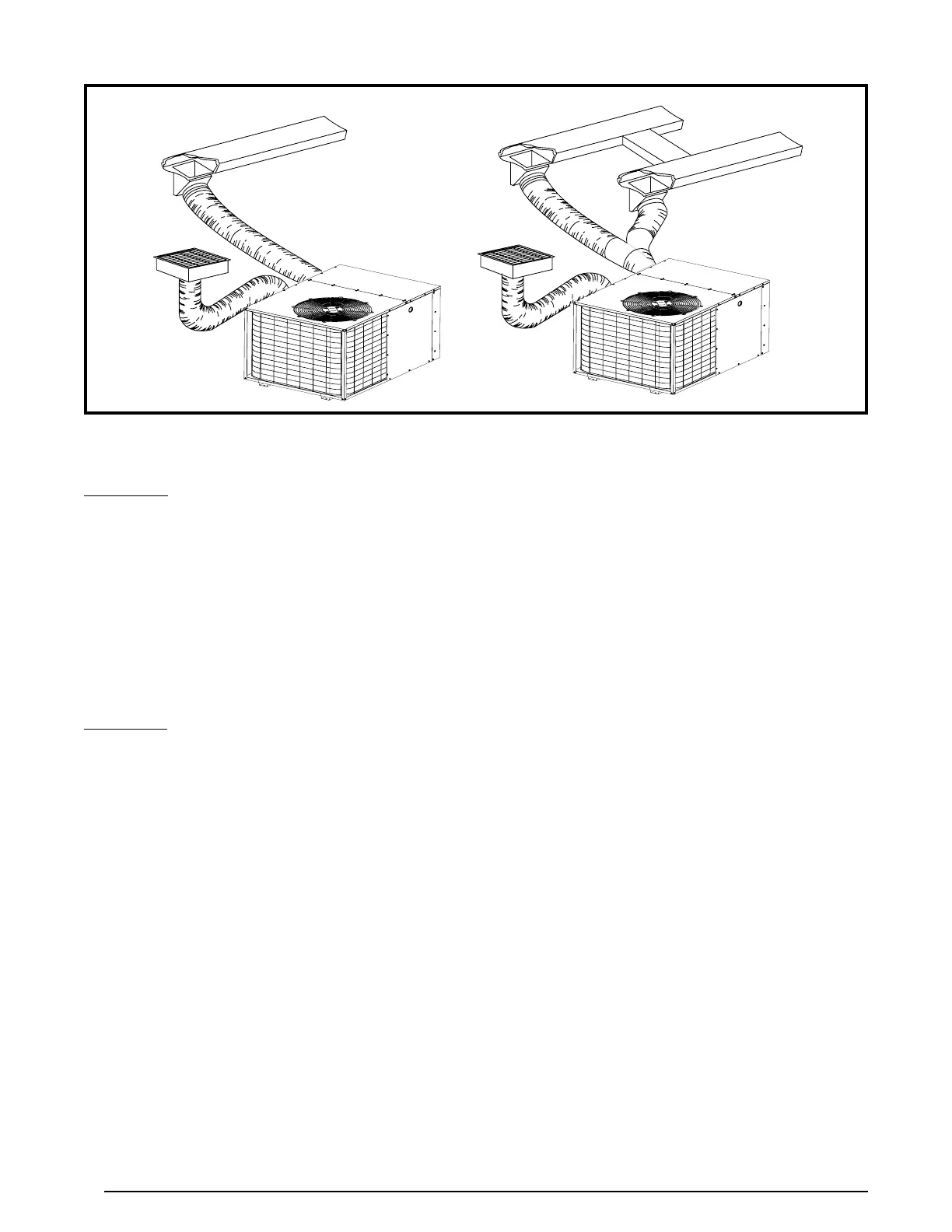
Figure 3. Typical Duct Applications
MULTIPLE DUCT APPLICATIONSINGLE DUCT APPLICATION
Supply Duct
1. Assemble the collar by overlapping the two ends.
NOTE: One end of the collar is slotted and the opposite
end has two small holes. Position the end with small
screw holes underneath the slotted end.
2. Fasten the collar ends with two self drilling sheet metal
screws.
3. Position the collar over the opening and align the 4 holes
in the collar with the 4 holes (or dimples depending on
model) in the rear panel.
4. Using self-drilling screws (10-16x.5), secure the collar
to the rear panel.
Return Duct
1. Assemble the collar by overlapping the two ends.
NOTE: One end of the collar is slotted and the opposite
end has two small holes. Position the end with small
screw holes underneath the slotted end.
2. Fasten the collar ends with two self drilling sheet metal
screws.
3. Position the collar over the opening. Align the four holes
in the collar with the four dimples or holes (depending
on unit model) in the panel.
4. Secure the collar to the rear panel using self tapping
screws (10-16x.5).
Connecting Return & Supply Air Flexible Ducts
• Flexibleductsmaybecuttotherequiredlengthand
spliced with sheet metal sleeves and clamps. Keep all
ducts as short and straight as possible. Avoid sharp
bends. Please follow all instructions packed with duct.
• Flexible ducts can be secured to the corresponding
collars with the provided clamps. After the inner duct is
connected to the collar, pull the insulation and plastic
sleeve over the connection and clamp. NOTE: To prevent
a loss in cooling capacity, make sure all connections
are tight.
• Homes with multiple supply ducts (or special
applications), a Y fitting is available for dividing the
supply air to different areas of the home for more efficient
cooling. NOTE: For maximum performance, insulate the
Y fitting.
Locating & Installing the Return Air Assembly
To simplify installation, locate and install the return air
assembly first. If desired, the return opening can be located
inside a closet with louvered doors that has an open area
equal to or greater than a 12” x 20” grille. The return air
grille can be placed in the wall of a closet and the ducted
into the filter box through a boxed-in area at the closet
floor level. Make sure the filter is readily accessible.
NOTE: The return air box with grille and filter (Figure 4,
page 7) should not be located in heavy traffic areas like
hallways or center of rooms. A good spot is in a corner or
under a table, if a minimum two inch clearance is available.
1. Start the installation from under the home by cutting a
small hole in the sub-floor. Determine how the floor joist
location will affect cutting the opening needed for the
return air box. NOTE: Floor joists are generally located
on 16” centers, leaving 14-3/8” between joists.
2. After measuring the return air box (approximately 12-
1/4” x 20-1/4”), cut the hole through the floor so that
the box will fit between the floor joists. Care should be
taken when cutting through carpeting to avoid snags.
NOTE: In most installations it will be necessary to cut
a similar hole in the fiberboard directly under the hole
in the floor. However, if the floor is more than ten inches
deep, it will only be necessary to cut a hole for the collar
on the return air box or for the insulated duct.
3. Set the box into the opening and fasten with screws or
nails.
4. Install the filter and return air grille in place.
 Loading...