
J
Joe LeeAug 21, 2025
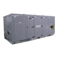
What to do if Nortek VENMARCES VHC-36 compressor will not turn on?
- KKimberly HinesAug 21, 2025
If the Nortek Heating System compressor will not turn on, there are several possible causes:* There may be no power. Ensure the main disconnect is on and measure the main terminal block for voltage.* The wiring might be incorrect. Verify if the compressor is wired correctly.* The controlled temperature may be lower (cooling) or higher (heating) than the thermostat setting. Adjust the thermostat setting.* The compressor may have failed, requiring replacement.