46 WLAN 2300 Series Outdoor Solution with Indoor Mounted AP
NN47250-503 (323847-C Version 02.01)
Based on these three scenarios, the following tables illustrate the additional amount of power loss that will be
realized when the extra cables and components are used to enable the access point to be mounted indoors and
the radiating element (i.e. antenna) to be mounted on the exterior of the premises. These additional losses need
to be factored into the overall system path loss equation when selecting placement of the access points and net
coverage areas. The current implementation of the WSS and WMS software does not allow for optimization of
performance by increasing the transmitter's output power to compensate for the added loss. That feature will
be available in a subsequent release of the WSS and WMS software. The values listed in the following tables
can be used to estimate a net reduction in total system power and coverage area.
For reference, a 3 dB reduction in power equates to halving the effective linear power. This translates to a
reduction in available range of a factor of four times. An additional loss of 3 dB would halve the power again
and reduce the range by another factor of four times. Hence, care should be taken to place the access point as
near to the point of debarkation from the premises as possible to reduce signal loss and optimize the outdoor
coverage area.
Table 9. Nortel WLAN 2300 Series Outdoor Solution configuration scenarios
Scenario 1 Scenario 2 Scenario 3
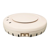
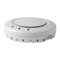
Configuration consists of the
AP 2330A or AP 2330B
connected to a 10-foot plenum
rated cable, which in turn is
connected to a Surge
Suppressor and then is
connected to one of the outdoor
rated antennas
Configuration consists of the
AP 2330A or AP 2330B
connected to a 10-foot plenum
rated cable, which in turn is
connected to a Surge
Suppressor, which in turn is
connected to a 10-foot outdoor
rated extension cable and then
is connected to one of the
outdoor rated antennas.
Configuration consists of the
AP 2330A or AP 2330B
connected to a 10-foot plenum
rated cable, which in turn is
connected to a Surge
Suppressor, which in turn is
connected to a 25-foot outdoor
rated extension cable and then
is connected to one of the
outdoor rated antennas.
Table 10. Loss associated with 10-foot plenum rated cable and surge
suppressor Loss associated Surge a
Connects AP
to Surge
Suppressor
Plenum Rated Cable (RG-58)
Component 10 ft Cable Surge Suppressor 10 ft Cable + Surge
Suppressor
Frequency
(MHz)
Loss (dB) Loss (linear) Loss (dB) Loss (linear) Loss (dB) Loss (linear)
2400 - 2500 -2.89 0.486 -0.13 0.029 -3.02 0.501
5150 - 5250 -4.96 0.681 -0.40 0.087 -5.36 0.709
5250 - 5350 -5.00 0.684 -0.38 0.083 -5.38 0.710
5470 - 5725 -5.23 0.700 -0.47 0.103 -5.70 0.731
5725 - 5850 -5.30 0.705 -0.57 0.123 -5.87 0.741