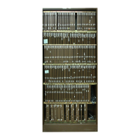
SCSI Crossover circuit pack (NT6M93xx) - Turbo only 14-5
DPP Hardware Component Replacement Guide DPP001 and up
31
Replace the rear panel. Reinstall the slotted pan head screws previously removed in step 4.
Note:
Align carefully before tightening to avoid stripping. Tighten the screws, alternating until all
are equally tight. Do not “cinch down” any one screw until all are properly aligned; no binding or
force needed to turn.
32
Clear any alarms on the DPP.
At the maintenance terminal, enter:
>RSERR ACT 00 (cr)
>RSERR STDBY 00 (cr)
Alarms will stay clear on the DPP if there are no faults.
33
Place the active processor unit in PRIME mode.
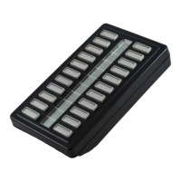
At the Switch and Status Panel of the DPP:
a. Press the A/B Select Switch to match the active processor.
b. Press the O/P Mode Select Switch to P.
c. Turn the Mode Switch to the right and release.
34
When all maintenance activities are complete, be sure to replace the front panel of the DPP
if removed.
Carefully line up the four captive screws of the front panel with their mounting holes.
Tighten the captive screws; but do not bear down.
At this time the procedure is complete.
Procedure 14-1
Replacing the SCSI XOVR circuit pack (NT6M93AA or NT6M93BA)
Step Description
Sheet 4 of 4
 Loading...