Installation 4-5
297–2011–208 02.01 Standard February 1999
Procedure 4-1
How to install the M522 (continued)
Step
Action
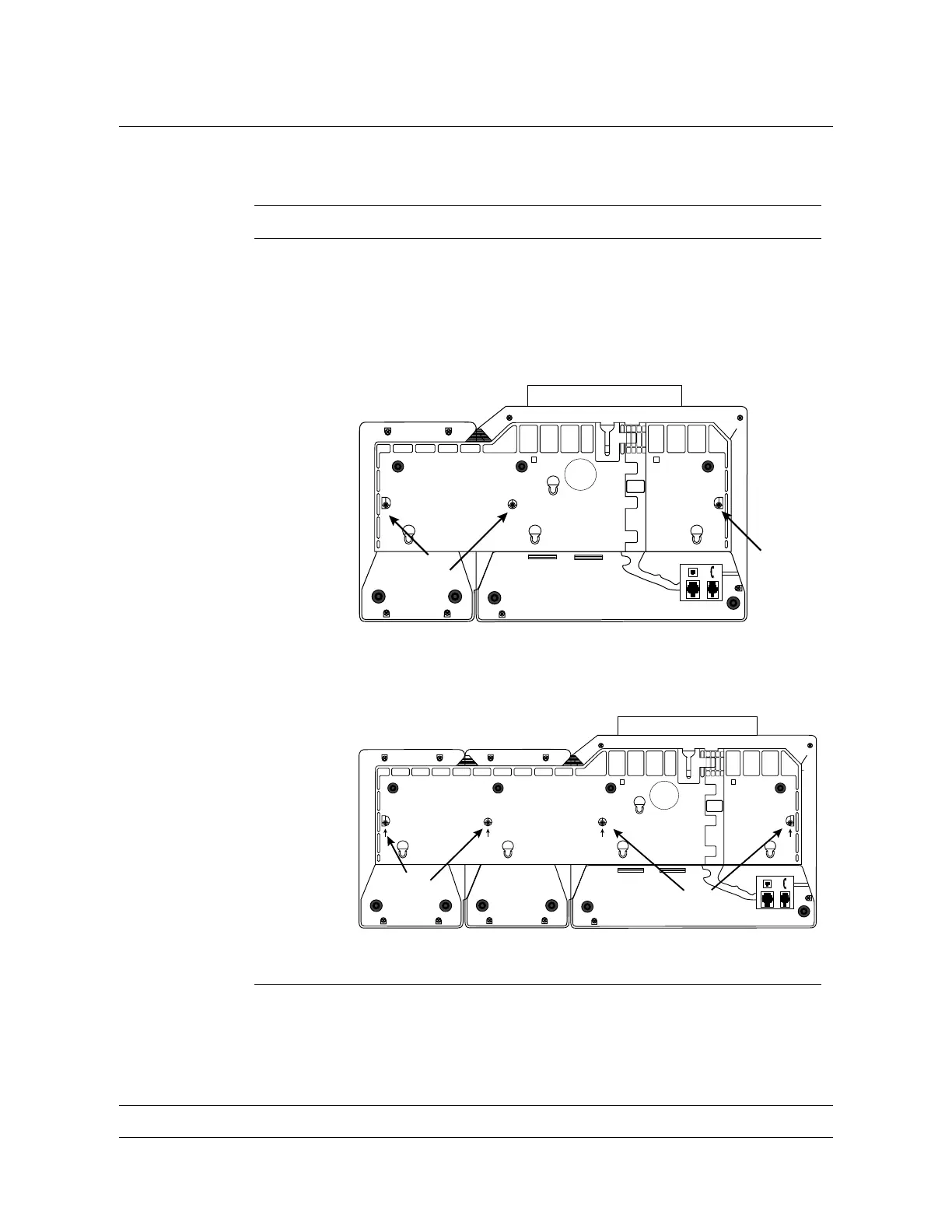
9 If you are connecting one M522 add-on module, position the
wedge-shaped base as shown in Figure 4-4. If you are connecting
two M522 add-on modules, position the base as shown in Figure
4-5. Align the plastic tabs in the base with the notches provided
on the M522 and telephone set.
Figure 4-4
Attaching the base (for one M522 module)
B
M5216/M5316
M522(1)
B
Figure 4-5
Attaching the base (for two M522 modules)
B
M5216/M5316
M522(1)M522(2)
B
—continued—



 To Next Page