Page 32 / 48
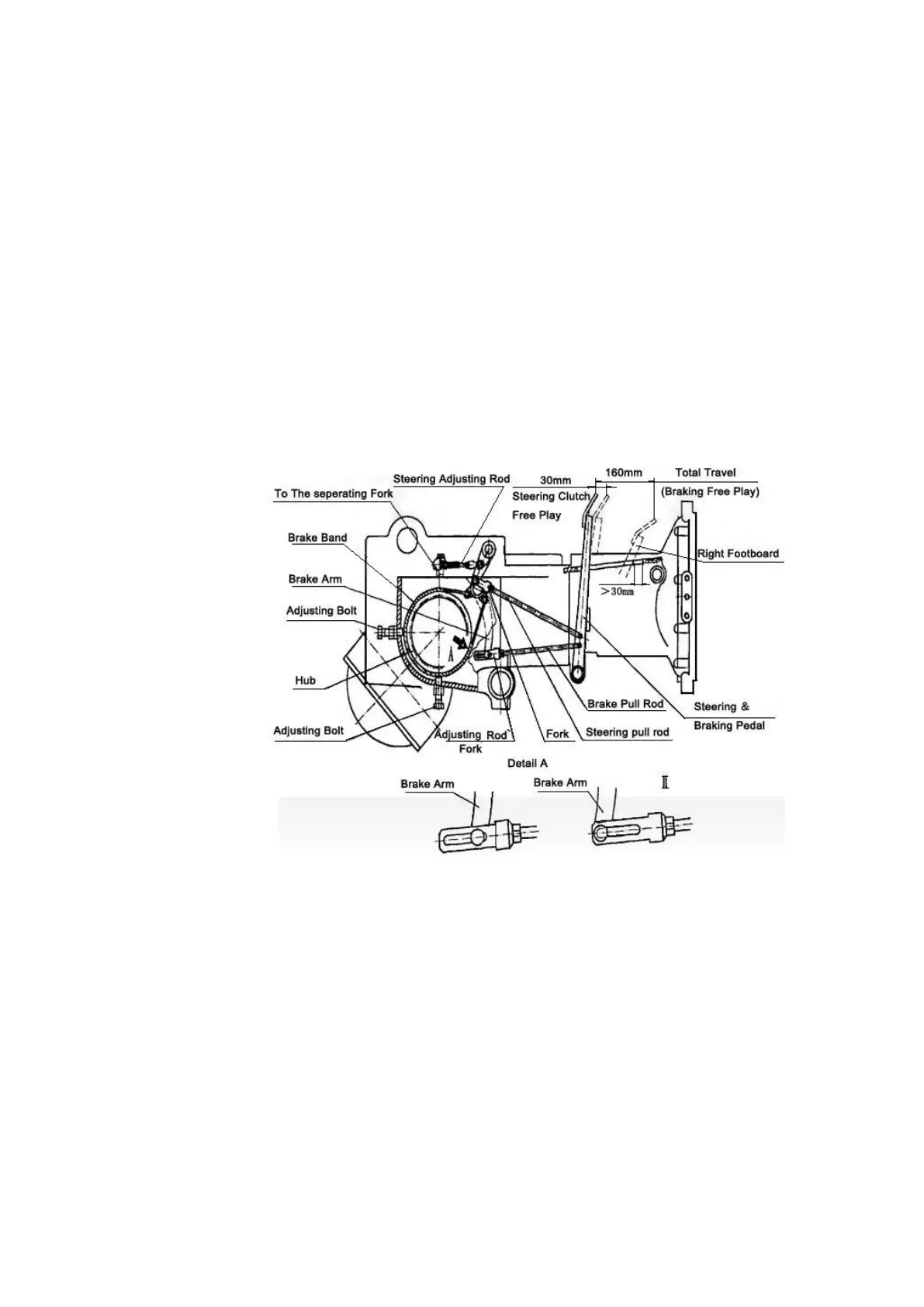
The steering is integrated with the brake. Controlling the brake pedals also controls the steering clutches
sequentially with the same pedals. Following steps instruct the operator on how to adjust.
a. Screw in the two adjusting bolts until tight and then screw out the bolts for 4/5 to 1 round. The clearance
between the brake and the hub should be 1.2-1.5mm. Tighten the two nuts.
b. Turn the adjustment fork to extend the brake pull rod and let the pin (at the end of the brake arm) move
toward the front of the groove, shown in Fig. 7.
c. Turn the fork to shorten or extend the steering pull rod or turn the steering adjusting rod to adjust the
steering free stroke to the stipulated value.
d. Turn the sequent fork to shorten the brake pull rod to adjust the braking free stroke to the stipulated value.
e. Push the brake pedal and steering pedal completely. The clearance between the pedal and groove end of
the footboard (right or left side) should be beyond 30mm and the pin at the end of the brake arm should
move back to the rear of the groove, as shown in Fig. 7.
f. Lastly, tighten all nuts on the steering adjusting rods, steering pull rod, and brake pull rod.
Notice: Tighten the brake and steering pedal completely. The steering clutch should be separated
completely and the bulldozer should be at a complete stop.
Fig. 8
Track Tension Device
When properly adjusted, tracks should have a sag of 2/3 to 1 in., as measured at approximately halfway
between the carrier roller and drive sprocket, as shown in Fig. 11. If the sag increases after a working period,
the track tension should be adjusted.
a. Stop the bulldozer on level ground and let the lower track flatten and straighten out the upper track sag.
b. Loosen the lock bolt of the adjusting screw.
c. Turn the adjusting screw till the track has a proper sag about 3/4 in., and then lock it up.
d. If the spring cap turns together with the adjusting screw, drive the arresting bolt into the groove of the spring
cap until the spring cap stops turning. After adjusting, turn the arresting bolt to its original position and lock
it up.
e. For the steel track bulldozer, after several adjustments, the idler may move forward to its extreme end. In
this case, take off one track shoe from the track chain, and then adjust the track tension.