DN-6834 • 07/20/04 — Page 3 of 4
APPLICATION
EXAMPLE 1
6834dia2.wmf
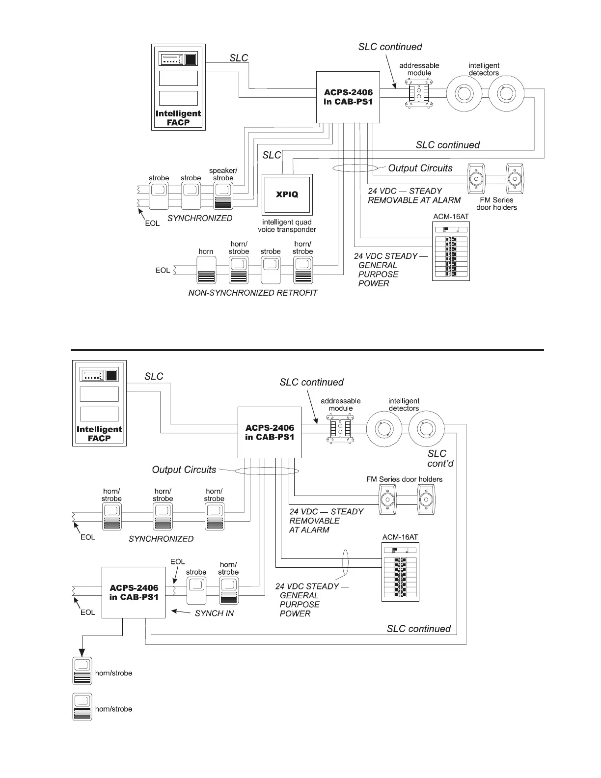
NOTES: 1) In this application, five SLC addresses are used: Point 1 = Trouble Monitor (used to notify control panel of ACPS trouble
condition); Point 2 = Output #1; Point 3 = Output #2; Point 4 = Output #3; Point 5 = Output #4. 2) SLC wiring only is shown in diagram.
NOTES: 1) In this application, six SLC addresses are used: Point 1 = Trouble Monitor (used to notify
control panel of ACPS trouble condition); Point 2 = Output #1; Point 3 = Output #2; Point 4 = Output
#3; Point 5 = Output #4; Point 6 = Electronic Signal Silence. 2) SLC wiring only is shown in diagram.
3) In this application, ACPS #1 and ACPS #2 have a “common” (all devices) sync signal. The NAC
output of ACPS #1 must be wired to the coded input of ACPS #2. 4) In this application, addressable
point #6 is used to signal ACPS horns to silence and let the strobes continue to run. System Sensor,
Wheelock, or Gentex sync devices only. This is a global selection.
APPLICATION EXAMPLE 2, master/slave
synchronization
6834dia3.wmf
 Loading...


