14 IQ-318/E/C Installation Manual — P/N 52864:J3 9/29/15
System Overview System Components
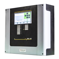
2.2.5 System Cabinet
The control panel is factory installed in its backbox. The lockable door is hinged on the left and
opens a full 180 degrees. Mounting methods include surface-mounting or semi-flush mounting on a
wall between 16 inch (40.64 cm) on-center studs. A trim ring option is available for semi-flush
mounting.
External measurements:
• Backbox: 18.12 in. (46.025 cm) width;
18.12 in. (46.025 cm) height;
5.81 in. (14.76 cm) depth.
• Door: 18.187 in. (46.195 cm) width;
18.40 in. (46.736 cm) height;
0.75 in. (1.905 cm) depth.
When using trim ring TR-320, mount backbox with at least 1 inch (2.54 cm) between wall surface
and front of backbox, to allow door to open fully past the trim ring. The TR-320 molding width is
0.905 in. (2.299 cm).
Additional Options
The IQ-318/E control panel provides space for one or two additional option boards to be installed,
as shown in Figure 3.3 on page 20. The IQ-318C fulfills ULC annunciation requirements; see IQ-
318C Canadian Applications Addendum for details. A variety of compatible annunciators are
available with their own backboxes; see Section 2.3, “Compatible Equipment”.
 Loading...