DAA2 & DAX — P/N 53265:A1 8/24/2011 105
Installation DAA Digital Audio Amplifiers
Batteries Within the Same Enclosure as the DAA
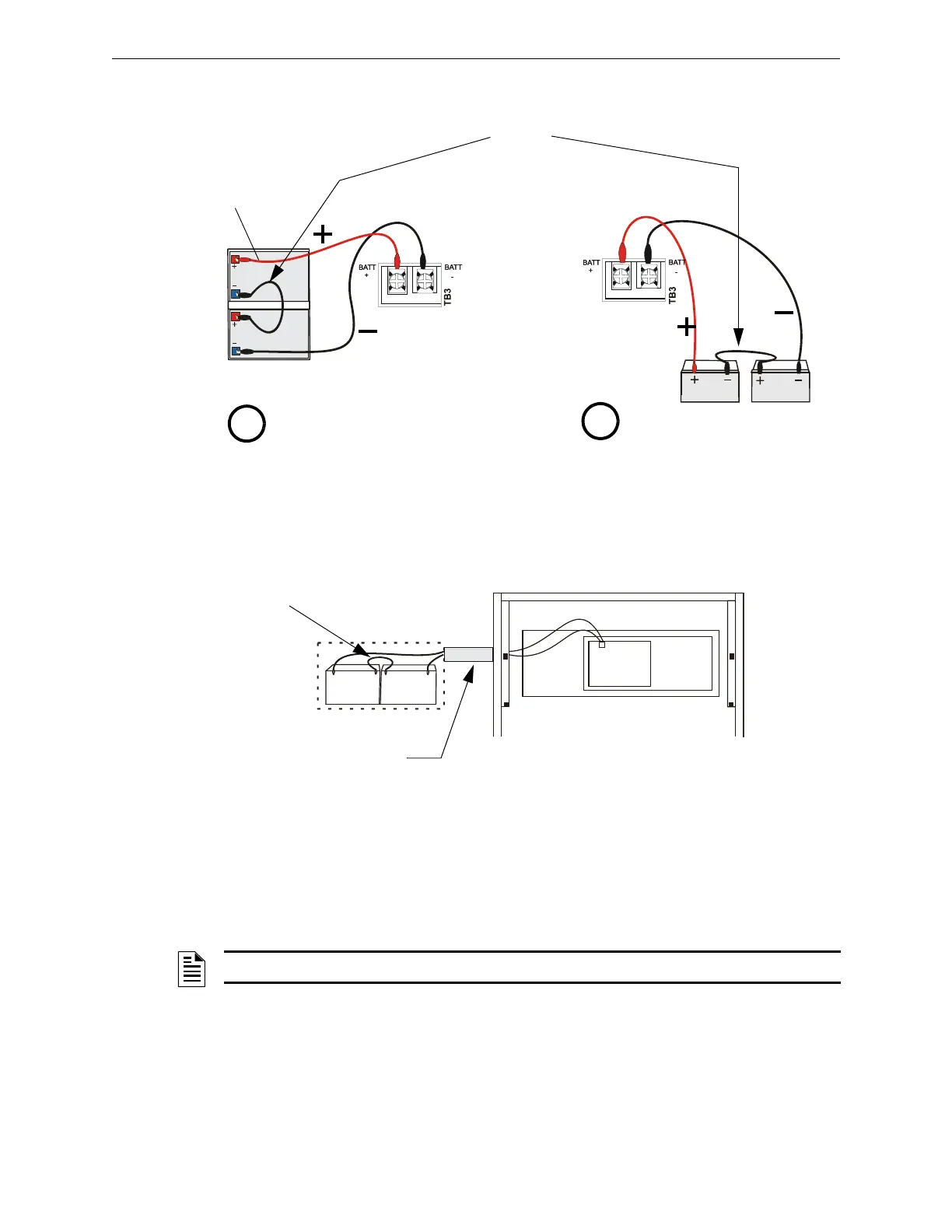
Refer to Figure C.12 for battery connections.
Figure C.12 Connecting Batteries to TB3 on the DAA-PS
Batteries Outside the DAA Enclosure
When the batteries are installed outside the DAA cabinet, connections are the same as in
Figure C.12. However, the battery cables between the two enclosures must be in conduit and the
enclosures must be within 20 feet (6.09 m) of each other within the same room.
Figure C.13 Using Conduit
Battery Sharing
Up to four DAAs may share a set of batteries. When DAAs share batteries, JP2 jumpers must be cut
on all but one DAA attached to a set of batteries, to disable Earth Fault detection. (Refer to
Figure C.3 on page 95.)
VeriFire programming must designate all DAAs but one as having the charger disabled.
Only one DAA should have its JP2 set to Enable, and only one DAA should have a working
charger. These DAAs do not have to be the same.
DAAPStobatts.wmf
Battery
Interconnect
Cable, P/N
71070
Leave disconnected
until after initial
system power-up.
Batteries in CHS-BH1, same
cabinet row as DAA
Batteries in different cabinet
row than DAA.
DAAPStobattsa.wmf
A
B
P/N 75560 (pos)
P/N 75561 (neg)
P/N 75621 (neg)
P/N 71071 (pos)
DAAbattexternal.wmf
DAA
Batteries
Conduit between
enclosures
Battery
Interconnect
Cable
Leave disconnected
until after initial
system power-up.
NOTE: This designation must be made for the 75 watt boards as well as the 50 watt boards.