96 DAA2 & DAX — P/N 53265:A1 8/24/2011
DAA Digital Audio Amplifiers Overview
Fiber Versions
Connection Locations
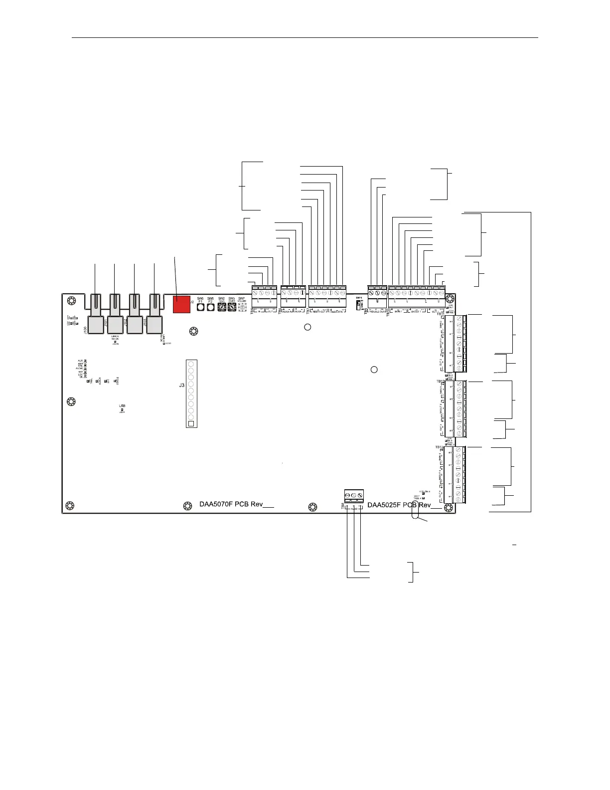
Fiber DAAs are each comprised of two boards; a larger rear board, and a smaller front power
supply board. Figure C.4 below shows the layout for the larger rear board. The connections for the
smaller front board, the DAA-PS, are the same for all DAAs, and are illustrated in Figure C.2,
“Connection Locations for Wire Version DAA Boards”.
Figure C.4 Connection Locations for Fiber Version DAA Boards
RISER (+) OUT
RISER (-) OUT
RISER SHIELD OUT
AUXA R +
AUXA R -
AUXA L +
AUXA L -
ALM IN
REF IN
ALM OUT
REF OUT
RISER (+) RTN
RISER (-) RTN
RISER SHIELD RTN
OUT 1 SHLD
OUT 1-
OUT 1+
TROUBLE OUT NO
TROUBLE OUT NC
TROUBLE OUT COM
BKIN 1+
BKIN 1-
BKIN 1 SHLD
BKOUT 1+
BKOUT 1-
BKOUT 1 SHLD
TB10
BACKUP
CKT 1
BKOUT 2 SHLD
BKOUT 2-
BKOUT 2+
BKIN 2 SHLD
BKIN 2-
BKIN 2+
TB9
Refer to
page 111
TB4 -
Alarm
Refer to
page 107
TB7 -
FFT Riser
Refer to
page 110
TB10, TB11, TB12, TB13
Speaker Circuits
Refer to page 112
TB10
SPKR
CKT 1
TB5
Refer to page 108
OUT 2 SHLD
OUT 2-
OUT 2+
BACKUP
CKT 2
SPKR
CKT 2
BKOUT 3 SHLD
BKOUT 3-
BKOUT 3+
BKIN 3 SHLD
BKIN 3-
BKIN 3+
OUT 3 SHLD
OUT 3-
OUT 3+
BACKUP
CKT 3
SPKR
CKT 3
BKOUT 4 SHLD
BKOUT 4-
BKOUT 4+
BKIN 4 SHLD
BKIN 4-
BKIN 4+
OUT 4 SHLD
OUT 4-
OUT 4+
BACKUP
CKT 4
SPKR
CKT 4
TB11
TB13
AUXB +
AUXB -
AUXB SHLD
DAA Board
TB8
AUX B
Refer to page 111
DAA_f_Bbrd1.wmf
TB12
USB
Connector
J2
Future Use
TXA
RXA
TXB
RXB
DAA board ID - DAA boards can be
identified by the silkscreening on the
board. This example shows a B
board. It is silkscreened with PCB
Note: If TB5 is a 3--screw terminal, the
DAA board is PCB or higher.