DAA2 & DAX — P/N 53265:A1 8/24/2011 21
DAA2 Installation DAA2 Digital Audio Amplifiers
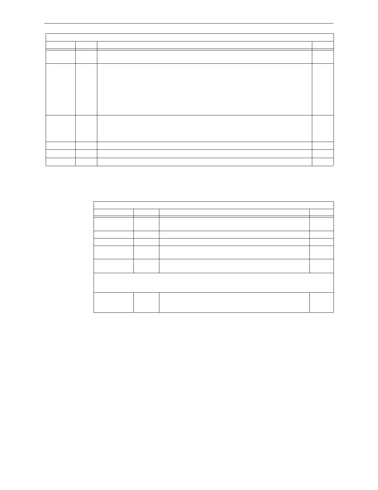
Switches
The switches described in Table 2.4 are for configuring the DAA2.
Table 2.4 DAA2 Switches
2.2 DAA2 Installation
2.2.1 Cabinet
The DAA2 arrives from the factory already installed on its chassis. A BDA-25/70V, NCM, or HS-
NCM, can be mounted on it. (Refer to Figure 2.5). A CHS-BH1 Battery Chassis may be mounted
to the left of the DAA2. The DAA2 chassis mounts in a CAB-4 Series cabinet, as well as in the
EQCAB Series backboxes.
Prior to installation,
• Review the installation precautions at the front of this manual.
• Installers should be familiar with the standards and codes specified in “Standards and Other
Documents” on page 9.
• Ensure all wiring will comply with national and local codes.
LOGIC
POWER
Green +5V logic power is OK. 1
TRBL Yellow Software-controlled as follows:
– OFF when the following system troubles are not present.
– 1 blink - AC FAIL. Priority 1, highest priority.
– 2 blinks - HIGH BATTERY. Priority 2.
– 3 blinks - LOW BATTERY. Priority 3.
– 4 blinks - CHARGER TROUBLE. Priority 4, lowest priority.
If multiple troubles are present, the highest priority trouble will blink until cleared, then the next
priority trouble will blink until cleared, etc.
2
EARTH
FAULT
Yellow When earth fault switch SW1 is enabled:
• Illuminates while earth fault is detected anywhere on the DAA2 except DAP A.
• If batteries are shared, illuminates when an earth fault is detected on any non-isolated circuits in
the sharing set.
3
AC Green AC power is on. 4
+24V AUX Green Illuminated while +24V auxiliary power is on. 5
+5V AUX Green Future Use 6
DAA2 Board
LED Name Color Description LED #
Table 2.3 DAA2 LED Indicators (2 of 2)
DAA2 Board
Name Switch # Description Default
2 WIRE/4 WIRE SW1 Changes FFT Riser indication to 2- or 4-wire, depending on
whether the riser is wired Class B or Class A.
2-wire
TENS SW2 BCD rotary address tens selection switch. Refer to page 41. 0
ONES SW3 BCD rotary address ones selection switch. Refer to page 41. 0
PRIMARY AMP SW4 ON is the normal state. OFF will induce an AMP FAIL trouble. Refer
to page 42.
ON
SIG SIL SW5 Pushbutton to silence speaker circuits during communication loss
with DVC.
N/A
CPS-24 Power Supply Board
GND FAULT SW 1 Ground fault detection switch. When this switch is set to enable it
will enable earth fault detection for Digital Audio Port A. Refer to
page 41
Enable