DAA2 & DAX — P/N 53265:A1 8/24/2011 31
DAA2 Installation DAA2 Digital Audio Amplifiers
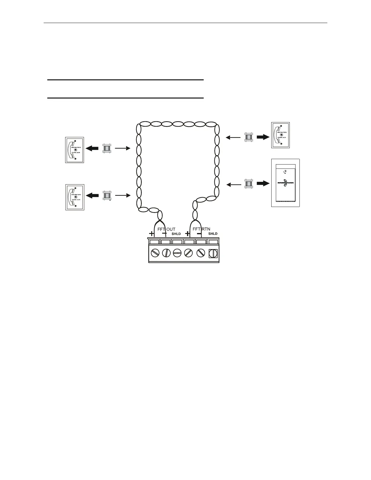
2. “Install FTM” not selected - FireFighter Telephones must be wired directly to the DAA2
FFT riser. The telephone point will be a DAA2 phone point. (AxT; where x = the DAA2
address.)
Programming must reflect whether the riser contains modules or not. (Refer to the programming
section of the DVC Digital Voice Command manual.)
Figure 2.16 FFT Riser (Class A Example)
An FHS firefighter handset may be used with the phone jacks in Figure 2.16. For a description of
the DVC firefighter telephone network operation, refer to the FFT appendix in the DVC Digital
Voice Command manual.
Telephone
Control Module
(option)
DAAPCCFFTriser.wmf
DAA2
AFAWS Fire
Alarm Warden
Station
TB7
Max wiring resistance
(including individual
telephone zone to last
handset) permitted is 50
ohms. 10,000 ft. (3048 m)
max. wiring distance at 14
AWG to last handset.
Telephone
Control Module
(option)
Telephone
Control Module
(option)
NOTE: If an FFT riser is not programmed for modules,
telephone modules are not options.
FPJ or RPJ-1
Firefighter
Phone Jack
FPJ or RPJ-1
Firefighter’s
Phone Jack
Telephone
Control Module
(option)