26 NFS-320/E/C Installation Manual — P/N 52745:M2 7/1/14
Installation NAC Connections and Releasing Circuits
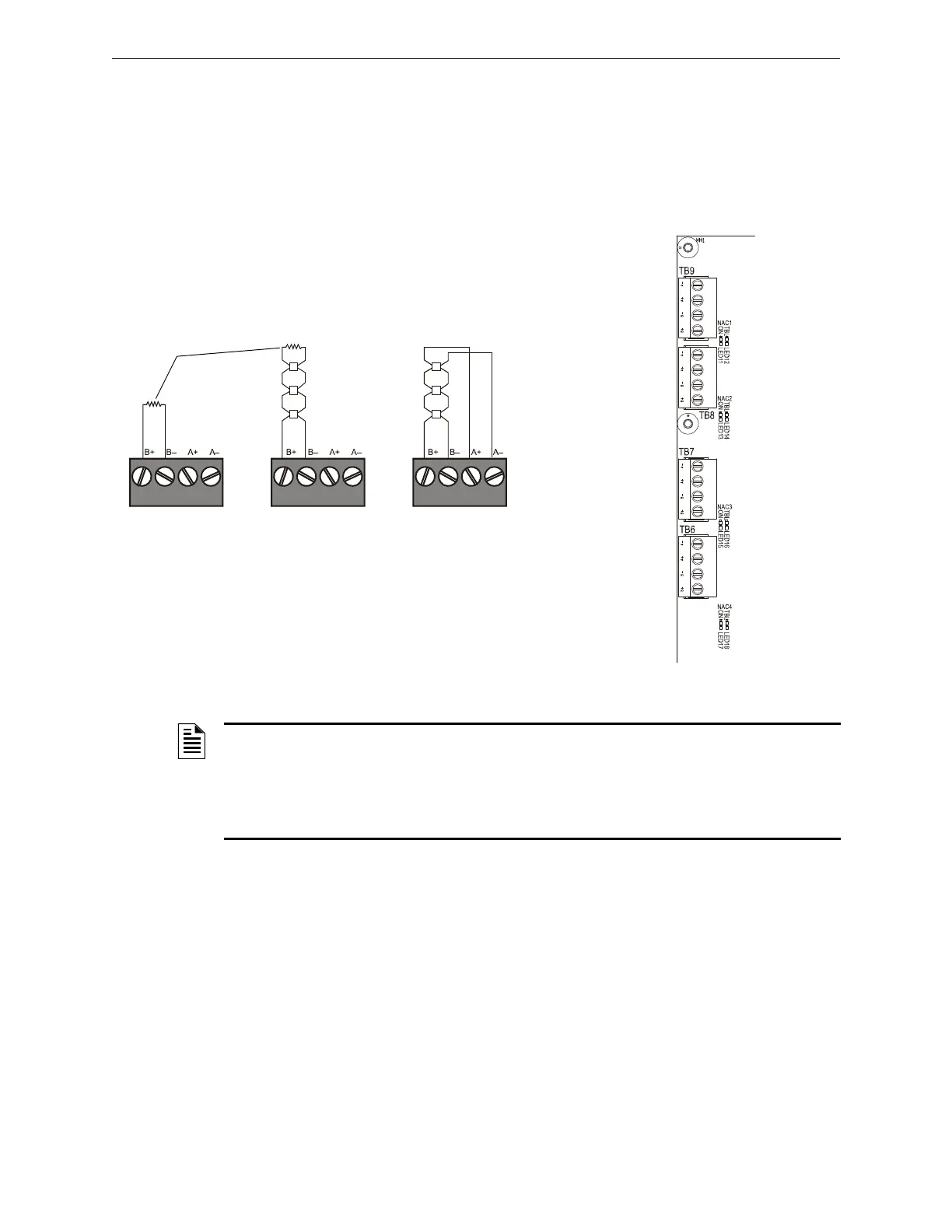
3.6 NAC Connections and Releasing Circuits
The control panel provides four NAC terminals as shown in Figure 3.9. Each can be configured as
Style Y (Class B) or Style Z (Class A) as shown in Figure 3.8. Each circuit can provide 1.5 A of
current, but the total current drawn from the main power supply cannot exceed 7.4 A in alarm
condition (refer to Table A.2). Additionally, TB2 (on CPS-24), TB10 and all 4 NACs share a
maximum of 3.0 A in standby and 6.0 A in alarm. NAC circuits are supervised and power-limited.
Use UL-listed 24 VDC notification appliances only (refer to the Device Compatibility Document).
nfs640-nacout.cdr
Style Y (Class B)
Connection
Style Z (Class A)
Connection
Unused Circuits
UL-listed ELR-2.2K,
1/2 W (supplied)
Figure 3.8 Notification Appliance Circuit (NAC)
Connections
Figure 3.9 NAC Terminals and NAC LEDs
TB9 - NAC#1
TB8 - NAC#2
TB7 - NAC#3
TB6 - NAC#4
CPU-320-NACS.wmf
A–
A–
A–
A–
A+
A+
A+
A+
B–
B–
B–
B–
B+
B+
B+
B+
NOTE: Any NAC can be programmed as a releasing circuit, and the releasing circuit must
be supervised; For more information, refer to Section 4.7 “Releasing Applications” in this manual
and the NFS-320/E/C Programming Manual. Refer to the Device Compatibility Document for UL-
listed compatible releasing devices. Sample connections for NAC terminals are shown in
Figure 3.8. Follow sequence of steps in Section 3.2 “Installation Checklist”, Table 3.1; this is part
of Step 4.
 Loading...


