Chapter2 Connection
Manual of NVEC400
- 8 -
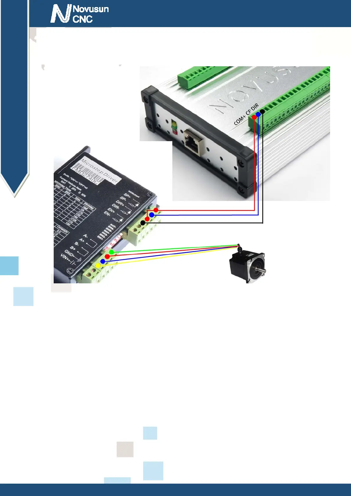
X/Y/Z/A/B/C axis from left to rught. Specific definition is
COM+/CPX-/DIRX-/COM+/CPY-/DIRY-/COM+/CPZ-/DIRZ-/COM+/CPA-/DIRA-/COM+/CP
B-/DIRB-/COM+/CPC-/DIRC- from left to right. The connection method with the stepper motor
driver see as Figure 2-3.
Figure2-3. Connect with steppermotor driver
2.2.3 Spindle control output
We define the interface from left are: GND(GND for VSO),VSO(0-10V adjustable speed
output),10VIN(supply by inverter or other spindle driver),GNDO(GND for
OUT1-3),OUT1,OUT2,OUT3.
Take Nowforeuer inverter as the example. Spindle control output and the inverter connection
showed as Figure 2-3.X1 control spindle RUN and STOP, AIN1 modify spindle's speed.
www.nvcnc.net
 Loading...