Chapter2 Connection
Manual of NVEC400
- 7 -
2.2 Product connection define and method
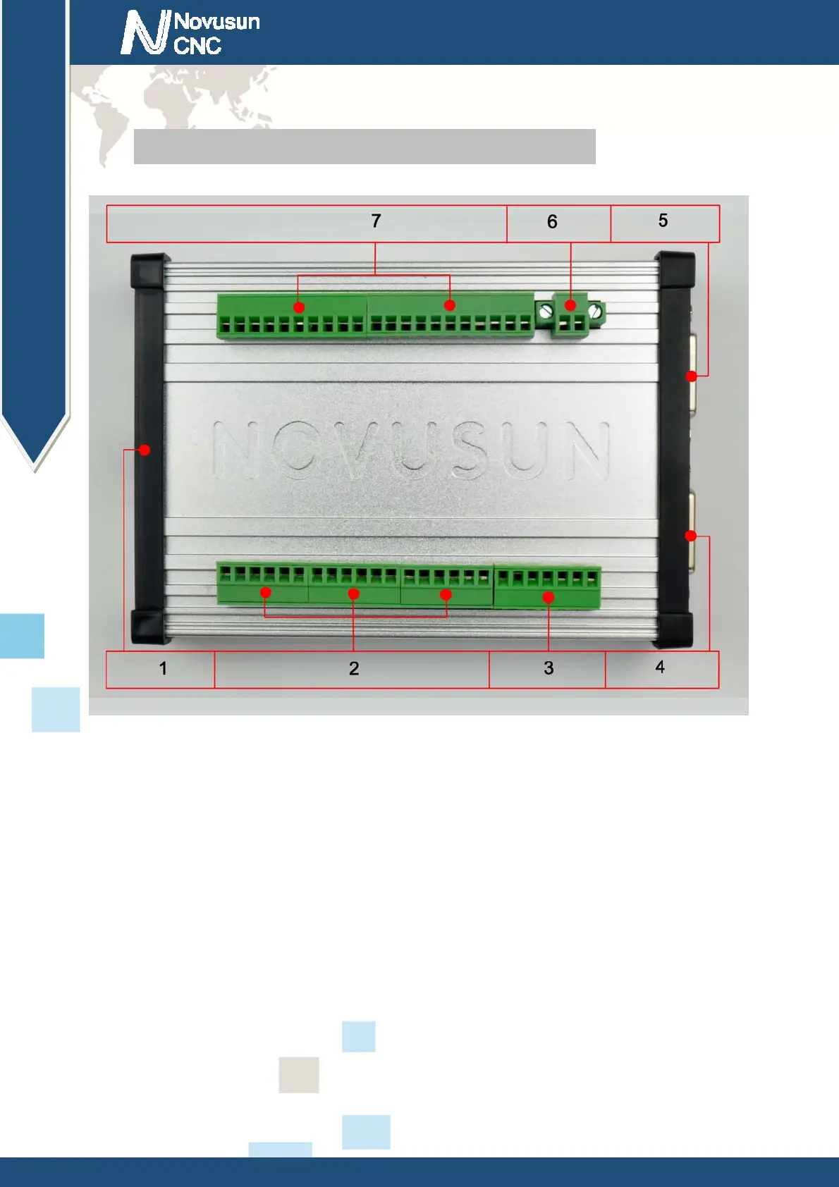
Figure2-2. Product wiring section and interface summary
As the Figure 2-2 showed, the connection of the controller includes power supply interface,
Ethernet connection interface, Stepper/Servo control output interface, spindle control output
interface, Estop and limited switch and tool setting input interface and so on. Now we descript
them in details as below.
2.2.1
Ethernet port
As Figure 2-2 showed,No.1 terminal block is Ethernet port, you can connect with the
computer through this interface. Then mach3 can control this card.
2.2.2 Stepper motor controller port
As Figure 2-2 showed,No.2 terminal block is steppermotor controller port, which is define as
www.nvcnc.net
 Loading...