Chapter4 Setting of software
Manual of NVEC400
- 25 -
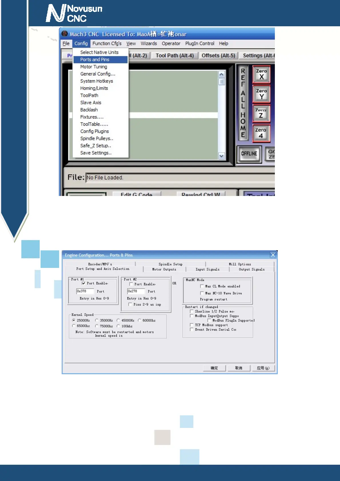
Figure4-5. Port setting intry
See as Figure 4-5
,
Click the sub-menu “ports and pins” of menu “Config” into Port Settings
dialog box.
Figure4-6. Pin&Port Dialog
The sub-pages you need to set include “Motor Outputs”, “Input Signals”, “Output Signals”
and “Spindle Setup”. First Click to enter “Motor Outputs”. This page is to select the stepper motor
control pin. Because our Ethernetmach3 interface board stepper motor signals are fixed, So here
only need to Select, no need to select the specific pin. See as Figure4-7
www.nvcnc.net
 Loading...