Chapter4 Setting of software
Manual of NVEC400
- 28 -
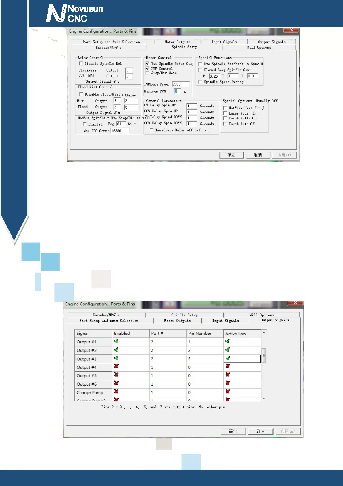
Figure4-10.
Spindle Settings dialog
Here we can configure the spindle rotates
、
CW Reverse
、、
CCW Mist Flood pin, See as
Figure4-10
,
They have been configured
、、、
as 1 2 3 4. Corresponding to output#1~output#4 in
Figure4-11.output#1~output#6 in Output Signal Setup dialog can be Configured into these 4
signals. Here we only configure CW/MIST/FLOOD. CW is controlled by OUT1. MIST is
controlled by OUT2. Flood is controlled by OUT3. Here we note correspondence between 2
page. Please select “use spindle motor output” if required PWM speed spindle. And select “ PWM
Control”. Our PWM pin fixedly arranged on a special pin on Stepper motor setting dialog.
Figure4-11. Spindle setting corresponds to the output configuration
www.nvcnc.net
 Loading...