J
Judith GravesAug 4, 2025
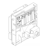
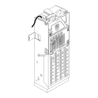
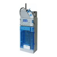
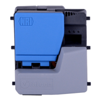
Why does my NRI G-18.mft coin validator not accept coins?
- SstevewalkerAug 4, 2025
There are several reasons why the coin validator might not be accepting coins. First, ensure the machine has power by connecting the battery to the control PCB and ribbon cable correctly, referring to the "Install coin validator and additional control PCB" section in Chap. 6 "Starting up". Also, check and replace the battery if the voltage is low, as described in the "Displaying battery voltage" section. Another reason might be that the return lever is pressed or stuck. Also check if the coin runway is dirty and needs cleaning. Finally, verify that the coin is not inhibited using the DIL switches or that only the narrow coin channel is enabled.