Handling and Mounting Precaution
取り扱いと取り付け注意事項
11
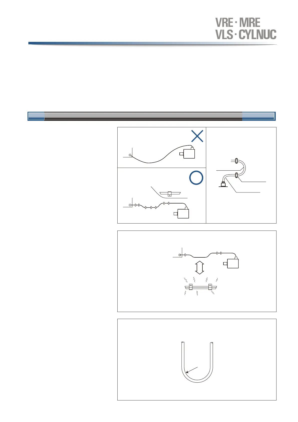
1)センサケーブルの配線方法
センサケーブルの配線は、コネクタおよびセン
サ接続部に過大な張力がかからないよう、ケ
ーブルをクランプしてください。
The sensor cable should be clamped as
shown in right figure to prevent excessive
tension from being applied to the cable
connectors.
アブソコーダ検出器およびシルナックシリンダの接続について説明します。
延長センサケーブルの長さは、アブソコーダ検出器およびシルナックシリンダとケーブルの種類、組合せるコントローラまたは変換器によって制限があります。コントロ
ーラまたは変換器の取扱説明書にてご確認ください。
The ABSOCODER sensor (or CYLNUC cylinder) connection is described below.
The maximum extension cable length varies according to the ABSOCODER sensor (or CYLNUC cylinder) and cable models being used.
Check with reference to the controller or converter operation manual.
Sensor cable wiring
2)センサケーブルの配線場所
センサケーブルは、動力線や大きなノイズを
発生する線とは300 mm以上離してください。
The sensor cable should be located at least
300 mm away from power lines and other
lines which generate a high level of electrical
noise.
Sensor cable location
3)センサケーブル可動範囲
ケーブルがU字屈曲の状態で移動する場合は、
ロボットケーブルを使用してください。この時
の曲げRは75mm(φ150)以上としてください。
If
the cable movement (When used at moving
component) is such that it is bent into a
U-shape, a robotic cable should be used.
The bend diameter should never be less
than 150 mm.
Sensor cable movable range
ケーブルクランプ
Cable clamp
300 mm
R75 mm or more
R75
mm以上
ケーブルクランプ
Cable clamp
R40
mm以上
R40 mm or more
R40
mm以上
R40 mm or more
配線
1
Wiring
4.配線上の注意事項
Wiring precautions
 Loading...