Installation & Operation Manual │ FTG
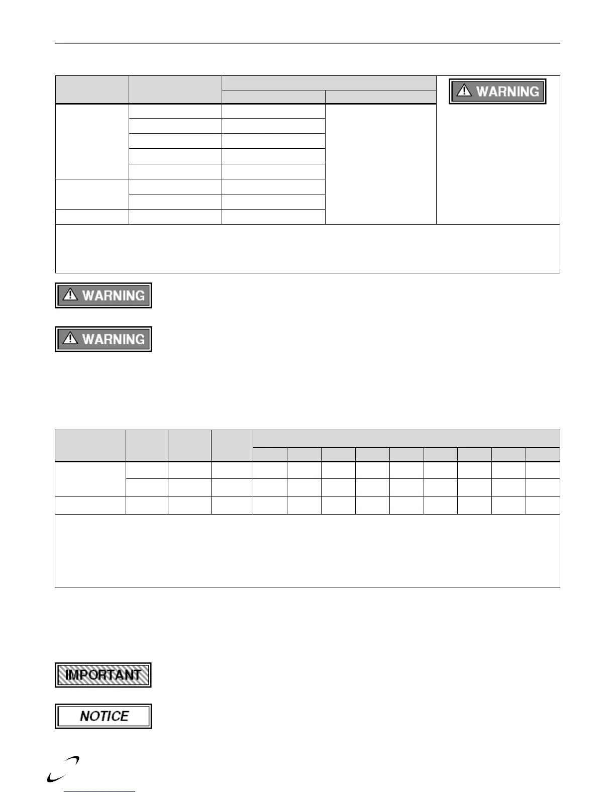
Exhaust-vent/Air-inlet Pipe Material
Table 4-4 Approved Vent and Air-Inlet Pipe Material
All Vent and Air-Inlet
materials installed on gas
fired appliances in CAN/US
must meet the Standards
listed in this Table. Failure
to comply could result in
fire, serious injury or death.
All venting material in
Canada must be
ULC S636 approved.
Notes:
1
Refer to Table 4-5 for Allowable Vent and Air-inlet Pipe Sizes and Lengths.
2
PVC venting (exhaust and air-inlet) is not permitted within the Closet/alcove of a Closet/alcove installation.
3
The Air-inlet does not require high temperature pipe material. Check applicable local codes for acceptable materials.
The use of cellular core PVC (ASTM F891), cellular core CPVC, or Radel®
(polyphenolsulfone) in the exhaust venting system is prohibited. Failure to follow these
instructions may result in property damage, personal injury or death.
Covering non-metallic vent pipe and fittings with thermal insulation is prohibited. Failure
to follow these instructions may result in property damage, personal injury or death.
Vent/Air-inlet Pipe Length Determination
Use Table 4-5 to determine the maximum pipe length that can be used. The table calculates 90º elbows, and 45º
elbows at 5 equivalent feet each.
Table 4-5 Allowable Vent and Air-inlet Pipe Size and Lengths
Number of Elbows (90’s or 45’s) and Equivalent Feet
Notes:
1
Minimum length of each the exhaust vent and combustion air-inlet piping is 5 feet equivalent.
2
For models FTG 600-800, the last 6 ft. of exhaust vent piping (vent termination) can be reduced to 4 or 5 in. diameter
vent pipe.
3
For models FTG 1200-2400, the last 6 ft. of exhaust vent piping (vent termination) can be reduced to 6 or 7 in. diameter
vent pipe.
Termination Options – Direct Vent Installation
The venting system of the FTG boiler may be terminated using field supplied piping to construct a “Two-Pipe”
termination, see Figures 4-2, 4-4(a) and 4-5(a); alternatively the venting may be terminated using a factory kit
selected from Table 4-6.
Venting Options - Due to potential moisture loading (build-up) along the exterior wall,
sidewall venting may not be the preferred venting option; see Figures 4-2(a), 4-2(c), 4-3(a)
and 4-5.
When sidewall venting, it is recommended to reduce the diameter of the exhaust vent at
the termination, to increase exhaust gas velocity, further directing it away from the
building. The final 6 ft. of exhaust vent can be reduced to a diameter of 4 in. for models
FTG 600-800, and 6 in. for models FTG 1200-2400; see Figures 4-2(a) and 4-2(c).
 Loading...