Installation and Operation Instructions Matrix
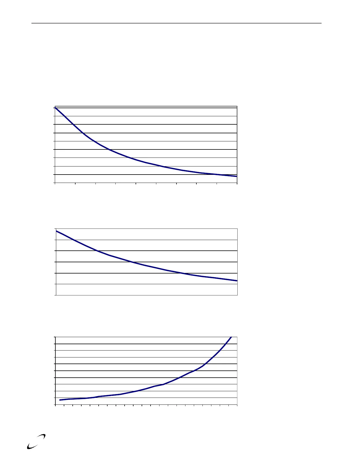
The following are the thermistor curves for diagnosing the water and outdoor air sensors:
Measure the resistance of the thermistor when disconnected.
Using the appropriate chart, find the resistance and move either vertical (water probe) or horizontal (air probe)
until the line is intersected.
Move 90 degrees to the corresponding temperature.
If the temperature is plus or minus 10 degrees, then the probe is operating correctly.
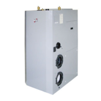
Figure 13.2 Matrix Thermistor Resistance Chart
1 Mohm Water Probe (Hi Temp.)
0
20
40
60
80
100
120
160 170 180 190 200 210 220 230
Figure 13.1 Matrix Thermistor Resistance Chart
1 Mohm Water Probe (Low Temp.)
0
0.25
0.5
0.75
1
1.25
1.5
1.75
2
2.25
50 60 70 80 90 100 110 120 130 140
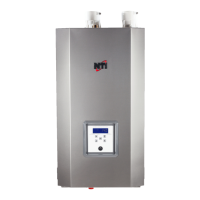
Figure 13.3 Outdoor 10K probe
0
10
20
30
40
50
60
70
80
90
100
100 75 50 25 0
Figure 20-1 Thermistor Resistance Chart – 1 MOhm Water Probe (Low Temp.)
Figure 20-2 Thermistor Resistance Chart – 1 MOhm Water Probe (High Temp.)
Figure 20-3 Thermistor Resistance Chart – 10 kOhm Outdoor Sensor