TFTN 085-199 Installation and Operation Manual
16.3.2.8 Sensor Configuration
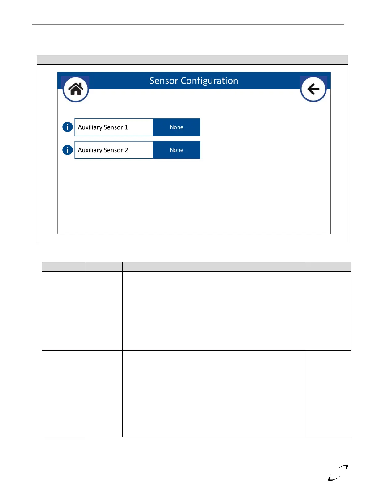
The Sensor Configuration menu must be accessed to configure the AUX1 NTC and AUX2 NTC inputs for use with a System,
Buffer Tank, or DHW Recirc sensor; see Figure 16-15 and Table 16-13.
Figure 16-15 Sensor Configuration Menu
Table 16-13 Sensor Configuration
Sets the functionality of input AUX1 NTC.
None – select if there is no sensor being connected to AUX1 NTC
System Sensor – select if connecting a system temperature sensor to
AUX1 NTC for direct boiler control of the system supply temperature.
Buffer Tank – select if connecting a buffer tank temperature sensor to
AUX1 NTC for direct boiler control of the temperature of an external
buffer tank.
Sensor must be 10k beta = 3977 NTC; an optional strap-on System
Sensor is available from NTI (P/N 84010).
Sets the functionality of input AUX2 NTC.
None – select if there is no sensor being connected to AUX2 NTC
DHW Recirc – select if connecting a DHW recirculation temperature
sensor to AUX2 NTC for direct boiler control of a recirculation loop
connected to the DHW IWH.
Buffer Tank – select if connecting a buffer tank temperature sensor to
AUX2 NTC for direct boiler control of the temperature of an external
buffer tank.
Sensor must be 10k beta = 3977 NTC; an optional strap-on System
Sensor is available from NTI (P/N 84010).