Tft Series Installation and Operation Instructions │Trinity
Lead Lag Instructions - Common
Plumbing – install as many as 8 Tft boilers in parallel in a primary/secondary plumbing configuration as
illustrated in Figure 11-1. Size common piping as per Table 11-1.
Boiler Pump – each boiler must have its own circulator (see Figure 11-1) which is controlled by its PUMP B
output; see Field Wiring Figure 12-1 and Table 12-1. The Boiler Pump must be sized according to Table 10-4.
Communication Wiring – using 3-wire cable, daisy-chain terminals DATA +, DATA – and DATA COM of each
boiler in parallel; see Field Wiring Table 12-2a and Figure 12-2.
System Sensor (Optional) – install a system sensor (NTI P/N: 84010) on the outlet (supply) pipe feeding the
heating system, see Figure 11-1. Wire the system sensor to SENSOR COM and SYSTEM of the Master Boiler;
see Field Wiring Table 12-2a and Figure 12-2. The system sensor automatically becomes the modulation
sensor for the boiler system, i.e. the control attempts to achieve setpoint temperature at the location of the
sensor. If a system sensor is NOT used, at the Master boiler set the applicable sensor input to Unconfigured
as follows:
Configure – Sensor Configuration – S10 (J10-7) sensor
Outdoor Sensor (Optional) – wire the outdoor sensor to SENSOR COM and OUTDOOR of any one of the
boilers in the cascade; see Field Wiring Table 12-2a and Figure 12-2. Note: only one outdoor sensor is
needed for the multiple boiler system.
Modbus Address – assign a unique MB2 Modbus Address to each boiler in the cascade. Access the MB2
Modbus Address setting via the System Identification & Access menu as follows:
Configure – System Identification & Access – MB2 Modbus Address
Master Enable – choose one (and only one) boiler in the cascade to be the Master, this boiler will receive all
control wiring and will be used for setting control parameters (see steps below). On this one boiler, set
Master enable equal to Enabled via the Lead Lag Master Configuration menu, accessed as follows:
Configure – Lead Lag Master Configuration – Master enable
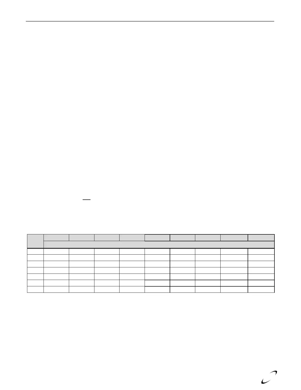
Table 11-1 Minimum Pipe Sizes for Multiple Boiler Applications
Note: Minimum pipe size based on assumed temperature rise of 25ºF at maximum firing rate.