Tft Series Installation and Operation Instructions │Trinity
System Disconnected
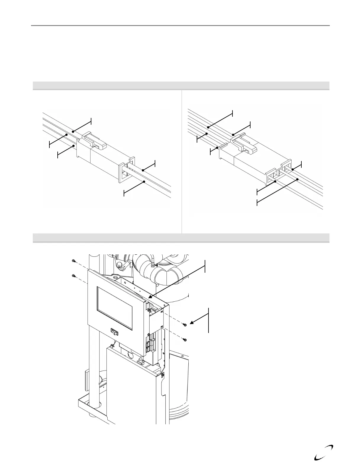
If the Touch-screen Display is not blank, but is displaying “System Disconnected!” in the middle of the screen,
ensure the 4 by 1 Molex connector, located behind the display at the top, is connected and that the wires are fully
inserted (see Figures 16-2 and 16-3). If the connector appears to be fine, check the wiring connections on the
back of the touch-screen display (remove display assembly, see Figure 16-3); Green, Red and Black go to
terminals 1, 2 and 3 respectfully.
Figure 16-2 Touch-screen Display Electrical Disconnects
Power Supply Connector (2 by 2)
Communication Connector (4 by 1)
Figure 16-3 Display Electrical Connection Access
Connectors Located
Behind Display at Top
Access the electrical connections in
the back of the display by removing
the screws securing the display
assembly to the control panel.