Trinity │Installation and Operation Instructions Tft Series
Table 3-1 Minimum Clearances for Installation and Service
Notes:
1
6” if surface is removable allowing a minimum of 24” [610 mm] clearance (i.e. closet installation). See Ventilation Air
Opening dimensions in Figure 3-1.
Closet/alcove installations in US and Canada require approved CPVC, Polypropylene or
Stainless Steel vent and air-inlet pipe and fittings (see Table 4-4); PVC is not permitted.
Failure to follow these instructions may result in damage or serious injury.
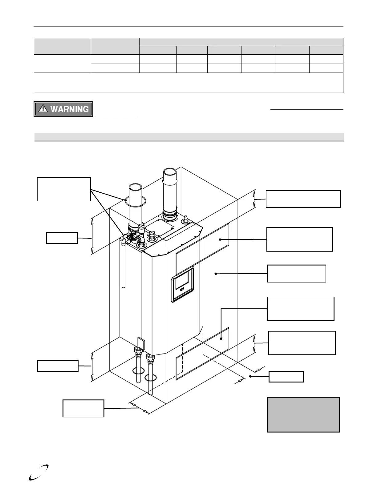
Figure 3-1 Closet Installation, Minimum Clearances
(Model Tft60-110 Shown)
Ventilation Air Openings
are not required if the
boiler area meets the
Recommended Clearances
listed in Table 3-1.
Bottom ventilation
opening Max. 6” above
floor / bottom
Top ventilation opening
Max. 6” below ceiling / top
Front = 6”
(if removable)
Removable surface /
closet door
Ventilation air opening
1in
2
per 1000 Btu/hr,
min. 100in
2
Ventilation air opening
1in
2
per 1000 Btu/hr,
min. 100in
2
Min. 1” clearance
for hot water and
vent pipes