21. 07. 20. Leaflet Number 671748
13
XBOXER XBC 10-65 Ecosmart Connect (CO) Control
Constant Pressure
Tapping
After Filter
Pressure Tapping
Before Filter
Pressure Tapping
AF
BF
After Filter
Pressure Tapping
Before Filter
Pressure Tapping
AF
BF
CP
Constant Pressure
Tapping
After Filter
Pressure Tapping
Before Filter
Pressure Tapping
AF
BF
After Filter
Pressure Tapping
Before Filter
Pressure Tapping
AF
BF
CPCP
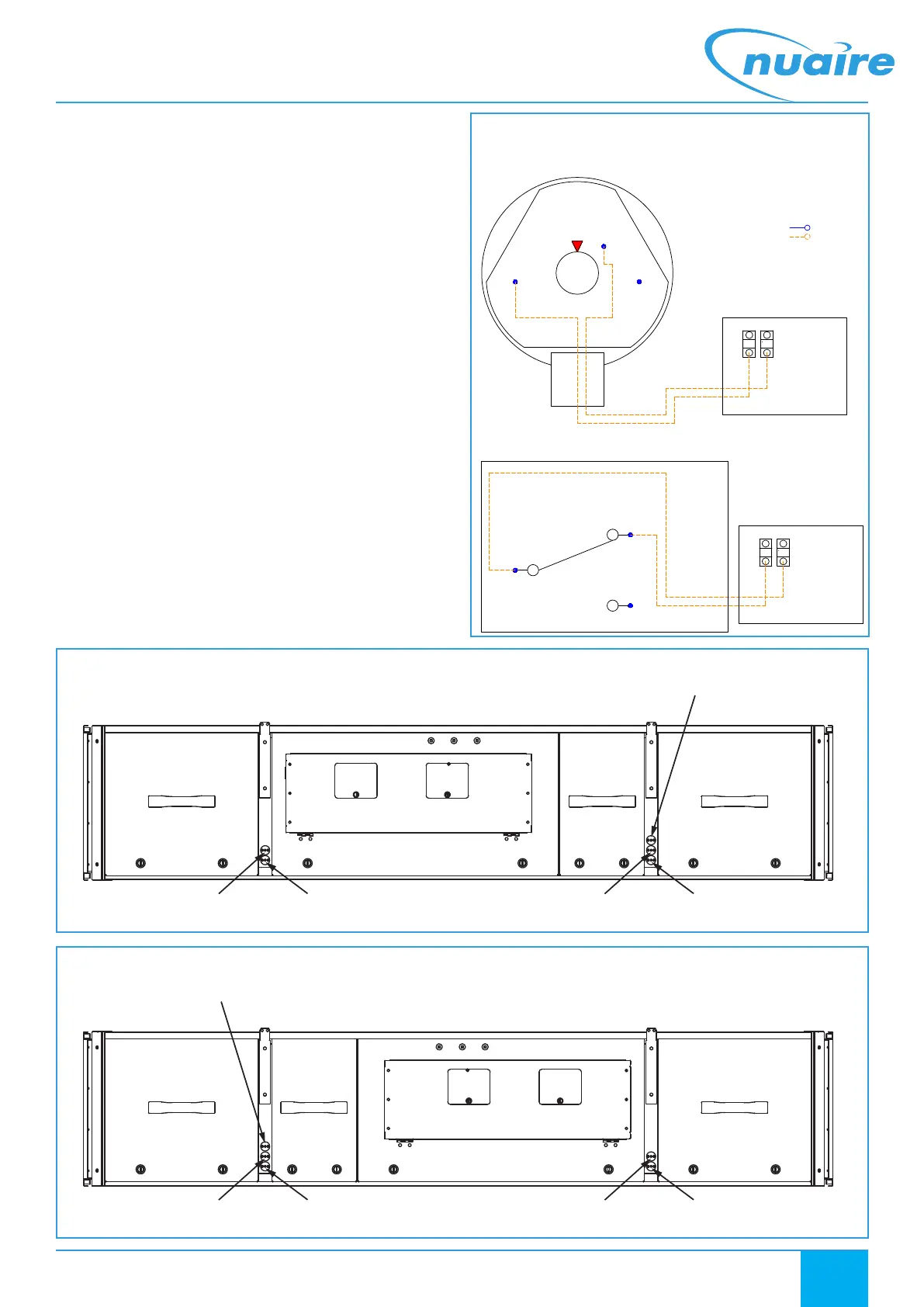
Figure 19. Access side view of pressure tapping layout of units with standard handing.
Figure 20. Access side view of pressure tapping layout of units with opposite handing.
• Connect a hose from the before filter (BF) pressure tapping to
socket P2 which is located on the middle section of the housing.
After you have installed the hoses, it is absolutely essential to check
them for tightness of fit at the connection points and to make sure that
they run without any kinks.
6.5.3 Wiring
The cable gland is designed for cables with alternative sheath diameters
of 7 mm or 10 mm. Only use these sizes. Otherwise the screw cable
connection cannot seal adequately. The connections are intended for
crimp-type sockets, 6.3 mm.
• Remove switch cover.
• Wire the main unit to the terminal block within the switch as per
the below wiring diagrams (see Figure 18) ensuring the feed line is
fused to suit Max 1.5A / 250 Vac.
• Refit switch cover.
6.5.4 Setting Switch Pressure
Make absolutely certain that there is no voltage on the electrical
connections before you carry out any setting on the pressure switch,
there is the possibility of an electric shock if you accidentally touch live
parts.
Nuaire recommend the pressure switch be set to trigger when the
filters experience a 125 Pa increase above the clean filter resistance for
the largest commissioned airflow rate. Use the adjustment dial to set
the pressure at which the switch will trip. When the pressure falls below
this set value, the switch returns to its resting position.
Sensor Diagram
Schematic Diagram
Internal Connection
Customer Connection
Pressure Sensor Internals
2 - NO
3 - C
1 - NC
Inside XBC Controls
Inside XBC Controls
XBC 25-85
Connect
Adapt Trend &
Adapt Siemens
Controls
T29 T30
*Note 1: NC has been blanked off.
*Note 2: Pressure setting of
125Pa above clean filter pressure
is recommended.
XBC
Connect
Adapt Trend &
Adapt Siemens
Controls
T29 T30
3 - C Contacts 2 - NO
when the difference
between positive &
negative pressure
is equal to the set pressure.
2 - NO
3 - C
1 - NC
*Note 2
Differential
Pressure
Setting
*Note 1
Figure 18. Dirty filter switch wiring.
 Loading...