XBOXER XBC 10-65 Ecosmart Connect (CO) Control
nuaire.co.uk 029 2085 8200
8.7 Configurable Mode (Via Switched Live 2)
The switched live 2 input is a configurable input that can be set to perform a
number of functions. The function is set via the network input Configurable
Mode SL2.
These functions will include the following:
•Fan boost (default setting)
This enables Fan Boost Mode
•Heater boost
The heater function will be enabled. Fan speeds will be increased where
necessary to keep supply temp at the heater boost setpoint. (Default 35°C).
•Extract Setback
When this SL2 is selected and active, the unit will force the extract fan to run
at a predetermined speed (30% default), regardless of all other demands.
Supply fan will operate at the normal speed. This mode can be used when the
unit is used in conjunction with a separate air extraction system.
8.7.1 Heat Boost
8.7.2 Fan Boost
When the control receives a heat boost signal, from either the network input
“Heat Boost” or “Configurable SL2” configured to “heat boost”, the heater
output will increase to 100%. The fan speed will be increased as required to
reach the heat boost setpoint.
When the control receives a boost signal, from either the network input
“Boost” or “Configurable SL2” configured to boost, the fans will run at their
individual boost speeds. Once the signal is removed the fans will run on for a
time defined by the boost run-on setpoint. Any demand in excess of the boost
speed will be ignored (apart from 3 speed override and purge schedule).
8.8 Temperature Control
8.8.1 Supply Temperature Control (Default)
8.8.2 Room Temperature Control
While an enable signal is present, this mode modulates heating, cooling &
heat exchanger bypass dampers with the aim of the supply air reaching the
temperature setpoint. Please note that heating and cooling outputs will only
function if the “Heating Type” or “Cooling Type” network inputs are set to
heating or cooling options.
The heat exchange bypass damper operates by calculating the supply air
temperature based on the return air temperature, the outside air temperature
and the heat exchanger efficiency (e.g. 13°C outside air temperature with a 23°C
return air temperature will give a supply air temperature of 20.5°C).
The control then chooses the damper position which requires the minimal heat/
cool tempering in order to achieve the setpoint.
While an enable signal is present, this mode modulates heating, cooling &
heat exchanger bypass dampers with the aim of the room air reaching the
temperature setpoint. Please note that heating and cooling outputs will only
function if the “Heating Type” or “Cooling Type” network inputs are set to
heating or cooling options.
When heating or cooling is required achieve the room setpoint, the output of
the heat/cool loops are split between ventilation demand or heat/cool demand
according to the following graphs. The intermediate “boost” zone is the area in
which a small amount of free-heat/cooling is available. In this zone, heating/
cooling is used to boost the free-heating/cooling.
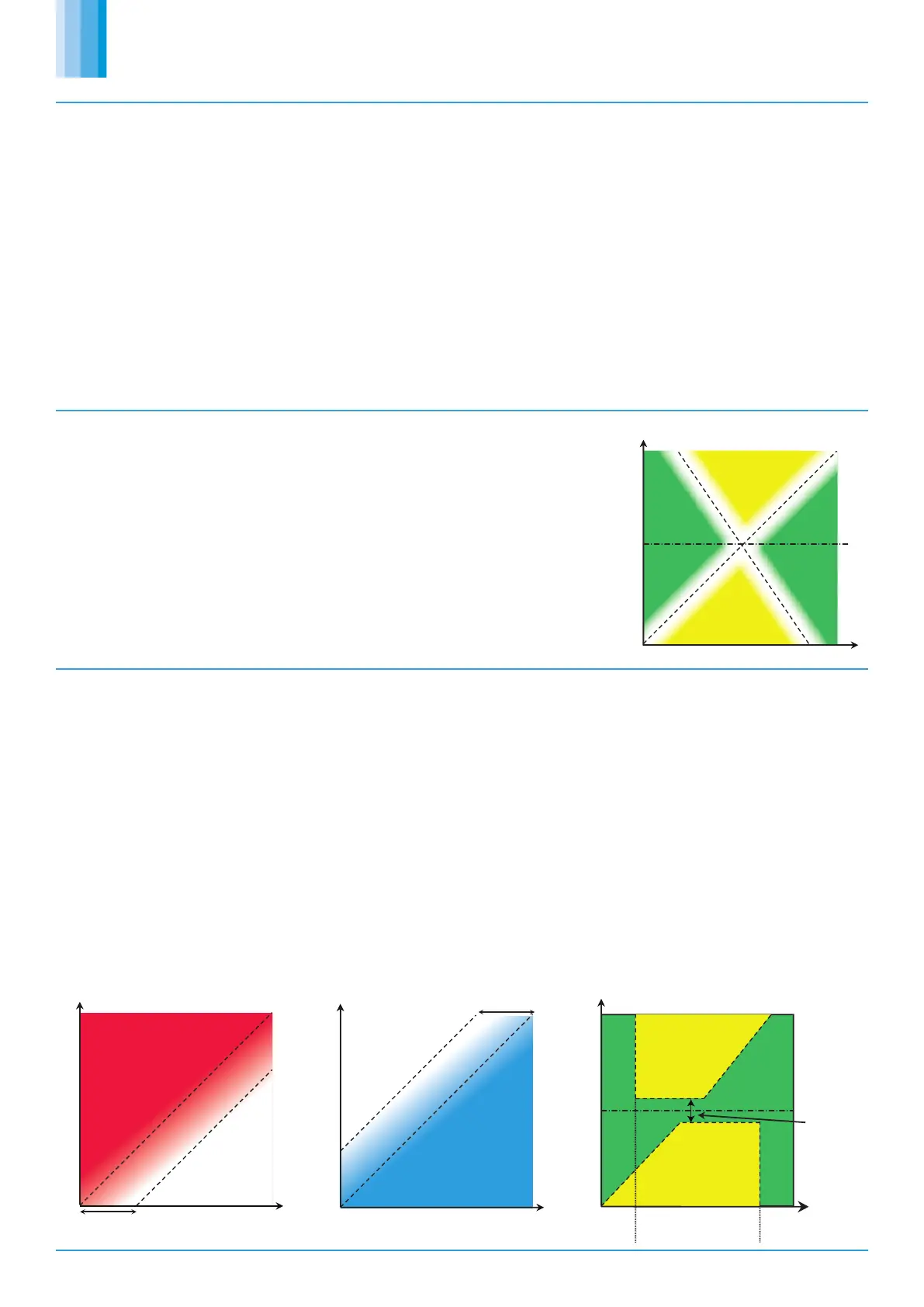
In room temperature control mode, the bypass damper is controlled according
to the following chart. A minimum supply air temperature limit is included to
stop the heat exchanger being bypassed when the air temp is uncomfortably
cold, even though cooling is required. In this case the heat exchanger will temper
the air for comfort. The reverse applies for the maximum supply air temperature
limit.
If the supply air temperature exits the min-max supply temperature range, the
unit will adjust ventilation, heating or cooling to compensate.
Note: Room temperature control will only be effective if the heater unit
is sized correctly for the space. If the unit is undersized, heating from an
external source may be required.
Room Air Tem p
Supply
Set
Point
Outside Air Temp.
HX
HX
Bypass
Bypass
Figure 22.
Note that the white are-
as indicate regions where
either heat exchanging
or bypassing will achieve
the same supply temper-
ature.
Room Air Tem p
Outside Air Temp
Free Heating
Vent Only
Boost Band
H
e
at B
oost
Zone
Room Air Tem p
Heating
Cooling
Boost Band
Free Cooling
Vent Only
Outside Air Temp
Cool Boost
Zone
Bypass
Bypass
HX
HX
Deadband
Room Air Tem p
Min Supply O utside Max Supply
Air Temp. Air Temp. Air Temp.
Room
Set
Point
Outside
Air Temp.
Figure 23.
8.8.3 Overrides
When the following conditions occur, the system will temporarily exit “Room
Temperature Mode” and enter “Supply Temperature Mode”.
•Trickle Mode with no enable signal. (Trickle deadband applies)
•Heat Boost Active
•Fan Boost Active
•Purge Mode Active
•3-Speed override by Room Module
 Loading...