XBOXER XBC 10-65 Ecosmart Connect (CO) Control
nuaire.co.uk 029 2085 8200
8.0 Description Of Control Strategy (SW-FAC2612-2-12A)
8.1 General
8.2 The Nuaire Unit Contains The Following Controllable
Items:
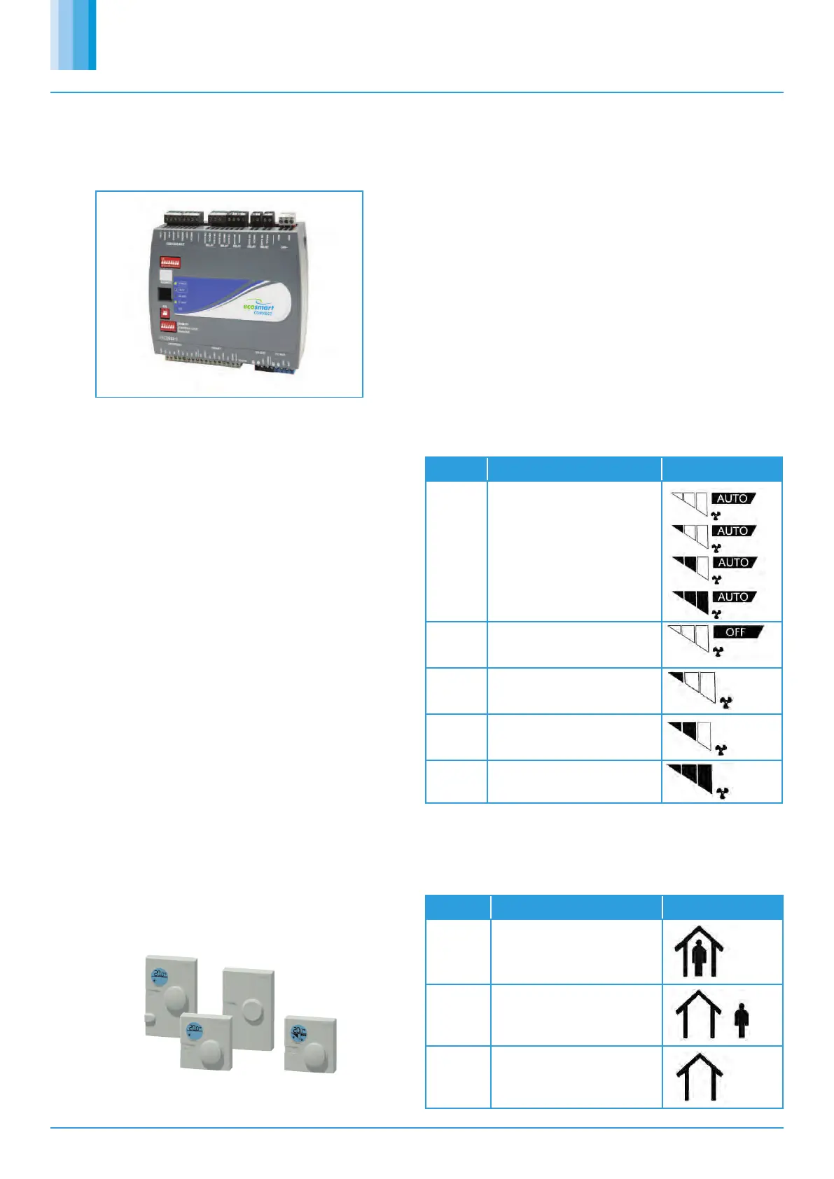
8.4 Room Modules
8.4.1 Room Module PIR
8.4.2 RM 3-Speed Fan Override (ESCO-TDFS Only)
8.3 Enable Signal
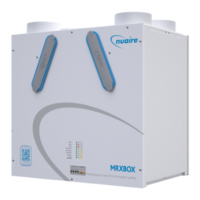
The system incorporates a preconfigured BACnet MS/TP enabled controller.
•Supply Fan
•Extract Fan
•Heat Recovery Bypass Damper (if applicable).
•Heating Coil (if fitted).
•Cooling Coil (if fitted).
•Inlet Damper (If fitted).
•Exhaust Damper (If fitted).
Ecosmart Connect allows the connection of multiple Room Modules which are
automatically detected and connect to the controller via a SA (Sensor
Actuator) MS/TP bus. See Network Accessory section for more connection
details.
When a Room Module PIR sensor is connected via the SA bus, the control will
automatically use this as an enable signal by default. There is a non-adjustable
minimum run-on time of 15mins for Room Module PIR's. This is in addition to
any software run-on times.
When a RM fan speed override is available it will override fan speed functions.
This function overrides any run-on time (except for electric heater heat
dissipation). While in override mode, the unit will ignore return air temperature
and set the supply air to the setpoint. Multiple fan override sensors are not
supported.
Whenever a fan-speed override Room Module is connected, the display will
automatically show the fan speed status at all times.
A timeout can be set for the fan mode to revert back to auto after a
predetermined time period. The setting Fan Override Operation and Fan
Override Timeout can be adjusted to achieve this.
The unit can be enabled via the following methods:
•Software switch (ENABLE) via local display or network.
•Switched live (230VAC) input, PIR etc.
•Volt free input contacts.
•Night Cooling / Summer free-cooling strategy.
•Scheduled via weekly calendar (Schedules are accessed and adjusted via
the ESCO-LCD).
•Fan speed override.
•Room module PIR sensor.
•Room module 3-fan speed button (While in low, med or high state).
•0-10v BMS input signal via IN5.
When the enable signal is removed, the unit will run on for a time defined by the
run-on setpoint.
If auto run-on is enabled, the unit will measure the each enable period and set
a dynamic run-on time proportionally to this value. This time is scaled by the
network input “Auto Run-on Scale Factor” and limited by the input “Auto Run-
on Max Time”.
Mode Operation Display
“Auto” The Controller will ignore the fan
speed override. Current Fan speed
will still be displayed.
“Off” The controller will override all
functions and stop the fans.
“Low” The fans run at low speed.
“Medium” The fans run at medium speed.
“High” The fans run at high speed.
8.4.3 RM Occupancy Display
If an RM sensor with occupancy display is connected, it will automatically
display the occupancy state as follows.
State Description RM Display
Occupied An enable signal is present
i.e. Fans are running.
Unoccupied No enable & no trickle
i.e. Fans are stopped.
Standby No enable signal but fans are
trickling.
 Loading...