1 - 6 en-938821/2
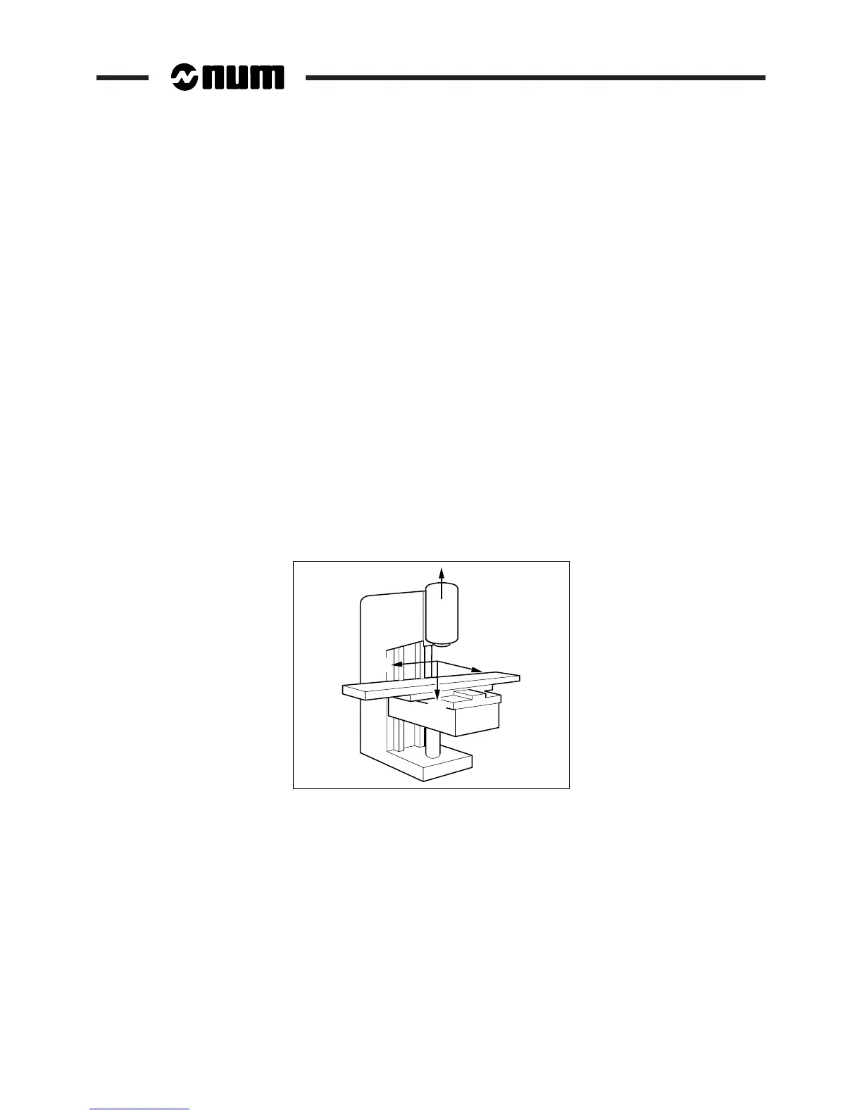
1.2.2 Machine Overview
The manufacturer defines the coordinate system associated with the machine in accordance with standard ISO 841
(or NF Z68-020).
The X, Y and Z axes, parallel to the machine slideways, form a right-handed rectangular cartesian coordinate system.
The coordinate system measures tool movements with respect to the part to be machined, assumed fixed.
REMARK When it is the part that moves, it may be more convenient to identify its
movements. In this case, axes X’, Y’ and Z’, pointing in opposite directions from
axes X, Y and Z, are used.
The direction of the axis of a machine depends on the type of machine and the layout of its components.
For a milling machine:
- the Z axis is the axis of the main spindle when this axis is parallel to one of the slideways,
- positive movement along the Z axis increases the distance between the part and tool,
- the X axis is perpendicular to the Z axis and corresponds to the largest excursion,
- the Y axis is perpendicular to the X and Z axes.
Rotary axes A, B and C define rotations around axes parallel to X, Y and Z.
Secondary linear axes U, V and W may or may not be parallel to primary axes X, Y and Z.
For more details, refer to the above-mentioned standard.
+Z
+Y'
+W'
+X'