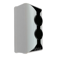
The NUMENS 407 Non-addressable Reflective Beam Line-type Smoke Detector is a professional safety product designed for smoke detection in large open spaces. It operates using a transceiver and a reflector, with the transceiver emitting a beam of light that is reflected back by the reflector. Smoke obscuring the beam triggers an alarm.
Function Description
The 407 detector uses a transceiver in conjunction with a reflector for smoke observation across a space. It provides detection over linear distances ranging from 8 m to 100 m, with lateral distances of 14.5 m. The detector is ideal for use in buildings with high ceilings such as atria, and large spaces like warehouses or shopping malls. It can also be used in applications where ceilings are too high for point-type smoke detectors or where point detectors are difficult to install and service.
Key features include:
- Long detection distance: From 8 m to 100 m at up to 14.5 m width.
- Single transceiver and separate reflector components.
- Quiescent condition indicator.
- Automatic compensation for lens contamination, alignment drift, ambient light conditions, and transmitted beam ageing. This ensures reliable operation even with environmental changes.
- Self-diagnostics function: Monitors internal faults and triggers appropriate indications.
- Separate Alarm and Fault relay outputs: Provides distinct signals for different events.
- Easy to install and commission.
The optical beam sent by the transceiver is reflected back to a receiver across the monitored space. A firmware algorithm within the unit calculates the receiver signal attenuation that may be caused by smoke particles absorbing or scattering the light and obscuring the beam path. The algorithm monitors the rate of received signal attenuation to differentiate between obscuration caused by smoke and other causes, such as objects in the beam path.
The detector automatically compensates for environmental obscuration and contamination. If the internal detection circuitry is defective, the device will release a Fault signal to the control and indicating equipment. If the optical path is obscured for more than 10 seconds by an opaque object, a yellow Fault LED and Fault relay will operate. If the optical path is restored within 30 seconds, the red Fire Alarm LED and the Alarm relay will operate. If the optical path is not restored, the fault signal will cancel automatically. If the detector has released an Alarm signal, the detector must be reset to clear the Alarm signal.
The 407 detector can be connected to a suitable CIE (Control and Indicating Equipment) in two ways:
- Direct Connection: For non-addressable CIEs, the 407 detectors can be directly connected to a detection zone transmission path.
- Indirect Connection: When connecting to addressable CIE or non-addressable CIE, the 407 detector can be connected via a 621-007 single input module, which provides a switchable DC 24 V supply to the 407 detector and transfers alarm signals to the CIE. The switchable DC 24 V supply voltage falls to 0 V when the CIE enters the Reset Condition, providing a simultaneous reset to the 407 line-type smoke detector.
Important Technical Specifications
Power:
- Operating voltage: DC (20 – 28) V
- Commissioning current: ≤ 20 mA @ DC 28 V
- Quiescent current: ≤ 12 mA @ DC 28 V
Quiescent condition indication:
- Alarm: Flashing red LED
- Obscuration sensitivity level: (1.3 ± 0.3) dB/m
- Alarm current (max): 22 mA @ DC 28 V
- Alarm indicator: Red LEDs
- Alarm N/O relay: 2.0 A @ DC 28 V
- Reset time: 15 s
Fault:
- Fault indicator: Yellow LED
- Fault N/O relay: 2.0 A @ DC 28 V
Environmental:
- Operating temperature: (-10 ~ +50) °C
- Operating humidity: (0 ~ 95)% RH, non-condensing
- Storage temperature: (-25 ~ +80) °C
- Storage humidity: (0 ~ 98)% RH, non-condensing
Miscellaneous:
- Detection distance: (8 – 100) m
- Detection width: 14.5 m
- Beam adjustment angle: ±6°
- Transmitted beam path angle: ±0.5° directional
- Alignment indicator (during commissioning): Green LED; yellow LED
- Dimensions (h x w x d): (206 x 95 x 95) mm
- Weight (with base): 405 g
- Ingress protection rating: IP-20, IP-66 (with glue-seal treatment)
Usage Features
Installation:
The installation process involves mounting the transceiver and reflector, ensuring proper alignment.
- Transceiver: The transceiver and reflector must be mounted on the same horizontal plane and parallel to each other. Optimal alignment is achieved when the received beam is strongest. The optical pathway must be directly to and from the reflector, and not received by the transceiver from other reflective surfaces.
- Mounting: The transceiver can be mounted directly on the wall surface or using a mounting bracket. The mounting bracket provides space for wiring to enter the rear of the transceiver base.
- Reflector: For distances between 8 m and 40 m, one 2 x 1 reflector is required. For distances between 40 m and 100 m, four reflectors are required.
Location Selection:
- General Criteria: Select an installation location that satisfies the following criteria: clean and dry, not subject to direct sunlight, away from a glass external wall, where the beam path is not obscured by moving items, and on a surface that the direction of transmitted beam does not vary due to vibration or changes in temperature.
- Ceiling Heights: For ceiling heights up to 40 m, mount the transceiver (25 – 600) mm below the ceiling or roof. For detectors installed (25 – 600) mm below the ceiling or roof, install detectors more than 600 mm below the ceiling or roof and reduce the spacing between beams to a quarter of the mounting height above the floor.
- Intermediate Heights: Where there is a risk that smoke may not rise to the ceiling or roof, additional detection may be provided at intermediate heights. The distance between detectors mounted at intermediate heights should be a quarter of the mounting height above the floor.
- Stratification: If stratification may occur because the smoke plume has insufficient energy to rise to the ceiling, or where smoke dilution is significant at greater distances from the source of the fire, intermediate line-type detectors located in spaces with high ceilings will detect a fire.
Pre-commissioning:
Before commissioning, ensure all equipment and tools are mounted and connected correctly.
- Check wiring for continuity.
- Check that all connections are made.
- Check that the correct number of reflectors are installed for the monitoring distance.
- Ensure both the transceiver and reflector(s) are securely mounted, oriented in the correct axis, and clear of obstructions.
- Check the configuration settings are correct for the monitoring distance and sensitivity requirements.
Commissioning:
- Detector Beam Alignment: Align the detector beam by removing the reflector protective cover, separating the transceiver cover, ensuring the transceiver is steady on its mounting bracket, connecting power, and placing the magnetic tool alongside the reed switch. The green Adjustment LED will flash or be on steady. Remove the magnetic tool.
- Manual Alignment: In alignment mode, a flashing Alignment LED indicates the reflected light beam is weak. To improve the received light beam strength, complete the following steps: remove the transceiver lens protective cover, adjust the adjustment screw, and tighten the locking screw.
- Automatic Alignment: Replace the transceiver cover. The Adjustment LED will remain on. Place the magnetic tool alongside the reed switch until the Fault LED illuminates continuously. Immediately remove the magnetic tool. Automatic alignment will commence. The following indications will be displayed after 10 seconds:
- Adjustment LED off: Received light signal is acceptable.
- Fault LED on continuously: Received light signal is weak.
- Fault LED off: After 10 seconds, the following indications will be displayed:
- Adjustment LED off: Received light signal is acceptable for the detector to enter the Quiescent condition.
- Fault LED flashes: The detector cannot enter the Quiescent condition. Repeat the manual alignment steps.
- Alarm Signal Test: Obscure the optical filter over the half of the transceiver lens for 30 seconds. Check that the red Alarm LED is on and the Alarm relay latches closed. Remove the obscuration filter from the transceiver lens. Reset the detector by removing power for ≥ 2 seconds.
- Fault Signal Test: Obscure the optical filter over the half of the transceiver lens for 15 seconds. Check that the yellow Fault LED is on and the Fault relay latches open. Remove the obscuration filter from the transceiver lens. Reset the detector by removing power for at least 2 seconds.
Troubleshooting:
- Cannot enter Alignment Mode: Check that the magnetic tool retains its magnetic property and can activate the reed switch.
- Fault signal cannot be cleared: Check that the beam path is clear of obstructions, check that the reflector is clean, check the beam alignment, and check that the ambient light conditions have not changed significantly.
- Alarm signal cannot be cleared: Check the beam alignment to ensure the receiver is receiving the reflected signal.
- Alarm signal released intermittently: Check that the detector is securely mounted on a stable surface, check the beam alignment, check for stray sources of electromagnetic interference, and check that the transceiver is shielded from direct sunlight.
Maintenance Features
Inspections:
- Conduct the following inspections every 6 months:
- Inspect detectors for any condition that is likely to adversely affect their operation, such as excessive deposition of dust or coating of paint.
- Inspect the area around the detector to ensure there is no interference to the beam.
- Every 12 months, disable the detector and the control and indicating equipment, then clean the transceiver lens and reflector with a damp cloth.
Tests:
- Following cleaning of the transceiver lens and reflector, conduct the following tests every 12 months:
- Test the release of the Alarm signal using the obscuration filter.
- Test the release of the Fault signal using the obscuration filter.