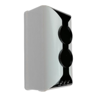
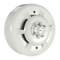
407 reflective beam line-type smoke detector
Installation and Service Manual
9
32-0061-r04_2020-10
© 2019, 2020 Ambest Electronics (Ningbo) Co Ltd. All rights reserved.
All specifications and other information shown were current at the date of publication and subject to change without notice.
Power terminals (D1, D2) connect to external 24V DC power supply. Power connection is required to fall to
0 V to initiate a reset of the 407 detector.
Alarm output terminals (K11, K12) and a series 470 Ω resistor is connected across the detection zone
transmission path conductors. When an alarm signal is released from the detector, the relay contacts will
close.
2.10. Indirect Connection Option
The 407 line-type smoke detector can be connected indirectly to control and indicating equipment using the
621-007 single input module to provide switched power to, and signal connections from the 407 line-type
smoke detector. Installers should refer to the relevant CIE installation instructions for power and signal
connection requirements.
An external DC 24 V supply is switched by the module to provide power to the detector. When the CIE enters
the Reset Condition, the voltage falls to 0 V and the 407 line-type smoke detector resets.
Alarm output terminals (K11, K12) are connected to the 621-007 input terminals. When an alarm signal is
released from the detector, the relay contacts will close.
The 621-007 single input module is installed and configured to the CIE in accordance with the installation
instructions (document number 32-0021). When connected to non-addressable CIE, the address setting DIP
switches on the module are not used.
Prior to commissioning, undertake the following pre-commissioning checks.
1) Check the wiring for continuity. Short- or open-circuit indications must be rectified before connecting to
CIE. All cable testing must be carried out with a multi-meter, not a meg-ohm meter when devices are
connected. Induced voltages greater than DC 1 V indicates possible cable problems or bad earth
connection and must be rectified before device connection.
2) Ensure all connections are made.
3) Check that end-of-line devices are fitted.
4) Check that the correct number of reflectors are installed for the monitoring distance.
5) Ensure both the transceiver and reflector(s) are securely mounted, oriented in the correct axis, and clear
of obstructions.
6) Check the configuration settings are correct for the monitoring distance and sensitivity requirements.
 Loading...