407 reflective beam line-type smoke detector
Installation and Service Manual
10
32-0061-r04_2020-10
© 2019, 2020 Ambest Electronics (Ningbo) Co Ltd. All rights reserved.
All specifications and other information shown were current at the date of publication and subject to change without notice.
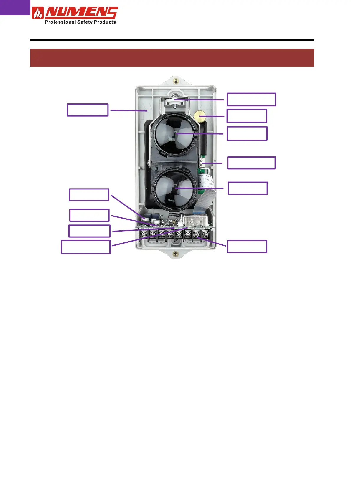
Fig. 14 – Transceiver with cover removed
4.1. Detector Beam Alignment
4.1.1. General
To align the detector beam, undertake the following actions.
1) Remove the reflector protective cover.
2) Separate the transceiver cover from the body by removing the M4 screws located at top and bottom of
the transceiver (see Fig. 1).
3) Ensure there is clear line-of-sight between the transceiver and reflector.
4) Ensure the transceiver is steady on its mounting bracket during alignment.
5) Connect power to the transceiver and enable it to stabilize for 2 min.
6) Place the magnetic tool alongside the reed switch. The green Adjustment LED will flash or be on steady.
7) Remove the magnetic tool.
4.1.2. Manual Alignment
In alignment mode, a flashing Alignment LED indicates the reflected light beam is weak (the slower the flash,
the weaker the received light beam). To improve the received light beam strength, complete the following
steps.
1) Carefully remove the transceiver lens protective cover.
2) Adjust the adjustment screw and the locking screw so that the Adjustment LED is on continuously.
3) Tighten the locking screw.
4.1.3. Automatic Alignment
1) Replace the transceiver cover. The Adjustment LED will remain on.
2) Place the magnetic tool alongside
○
M
(marking the location of the reed switch) until the Fault LED