407 reflective beam line-type smoke detector
Installation and Service Manual
8
32-0061-r04_2020-10
© 2019, 2020 Ambest Electronics (Ningbo) Co Ltd. All rights reserved.
All specifications and other information shown were current at the date of publication and subject to change without notice.
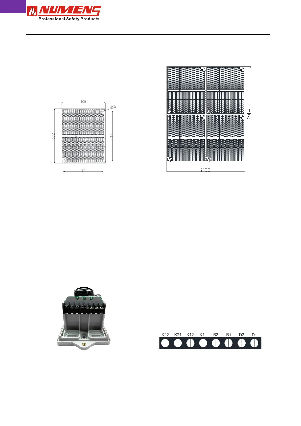
2.7. Reflector
If the distance between the transceiver and the reflector is (8 ~ 40) m, one 2 x 1 reflector is required. If the
distance between the transceiver and the reflector is (40 ~ 100) m, four reflectors are required (see Fig. 10).
Fig. 10a – Single 2 x 1 reflector
Fig. 10b – 4 x 2 reflector matrix
To install the reflector complete the following steps.
1) Drill two holes and install 6 mm wall plugs.
2) Fix the reflector to the wall using four ST4 x 30 screws.
2.8. Wiring
Wiring should be installed in accordance with National Standards and wiring regulations. The maximum
cross section of cables compatible with the device is 1.5 mm².
Terminate power and signal wires to the terminals (see Fig. 11) as follows.
Fig. 11a – Wiring terminals
Fig. 11b – Wiring terminals
2.9. Direct Connection Option (for Non-addressable CIE)
TThe 407 line-type smoke detector can be connected directly to non-addressable control and indicating
equipment detection zone transmission paths. Installers should refer to the relevant CIE installation
instructions for power and signal connection requirements.