116 OPI_SMART LIFT 2.30 SL-2.35 SL-2.40 SL - HYMAX S 3000-S3500-S4000_V1.2_DE-EN-FR-ES-IT
• Make sure that there is no residue of the cleaner
on the lift.
• Dry the lift with a cloth and spray it with a spray
waxoroil.
• Moving parts (bolts, bearing zones) are to be lu-
bricated or oiled according to instructions.
• Whencleaningtheworkshopoorensurethatno
aggressive cleaning materials come into contact
with lift surfaces. Permanent contact with any
kind of liquid is prohibited.
7.3 Readjustmentofthepolyexbelt
When exchanging the drive belt, the belt tension
must be readjusted. For this, remove the v-belt cov-
er.
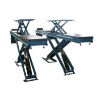
Figure 12: V-belt cover
(version with riser)
1: Column
2: Riser
3: V-belt cover
4: Lift spindle
Subsequently the v-belt tension on the tensioning
elementisreset(gure14).Forthis,the3fastening
screws of the motor (Figure 14, no. 1) are slightly
relaxed by one rotation. On the adjusting screws
(Figure14,no.2)thev-beltcannowberelaxedor
tensioned accordingly.
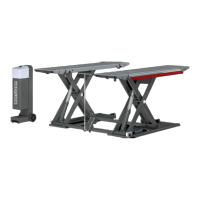
Figure 13: Position of the drive belt
1: Riser; (optional)
2: Tensioning elements to readjust
the belt tension;
3: Grooved pulley;
4: Polyex belt (drive v-belt)
5: Drive shaft motor
Figure 14: Setting the v-belt tension
1: Motor fastening screws
2: Alignment screws for v-belt ten-
sion
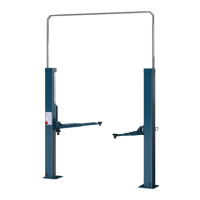
Figure 15: Accessory part
The polyex belt is set to the corresponding belt
deection with the aid of accessory parts (Figure
15); to be purchased from Nußbaum Hebetechnik
GmbH & CO.KG.
• Before setting the v-belt, the measurement de-
vice is to be placed on a at solid surface and
pusheddownwardsuntilthestylusislayingaton
the smooth surface.
• Afterwards null the dial gauge, meaning the outer
ring of the dial gage is to be turned so the pointer
is at zero.
Figure 16: Measurement instrument
Figure 17: Place the dial
gauge on the belt
• The measurement device, as can be seen in Fig-
ures16and17onthepolyexbelt.
• The dial gauge may only be turned a minimum of
1rotation(1mm)toamaximumof1.5rotations
(1.5 mm) anti-clockwise.
• The fastening screws are to be placed into the
starting position again.
7.4 Check/exchangetheliftnutsystem
Optical wear measurement:
! Catchbarxation“Safetykit”mustbeintegrat-
ed, see Section 9.1.
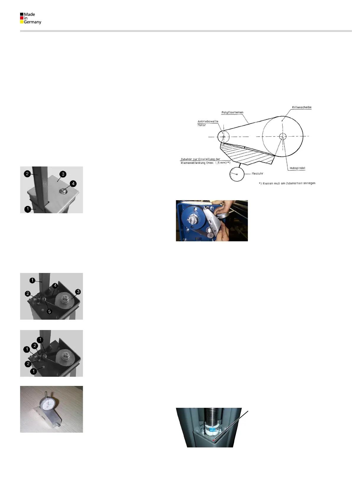
To check the carrier nut, the cover of the lift spindle
must be removed. A carrier nut wear gauge pin is
integratedintothecarrierplate.Thismustbeush
with the upper edge of the carrier plate (in the lift-
ing rail, top) - see Figure below. If the pin peaks out
2 mm from the top, the carrier nut and the follower
nutmustbeexchanged.
Figure 18: The lift nut pin is pro-
vided with a sealing wax
 Loading...