EasyManua.ls Logo

Nussbaum SPRINTER - User Manual

Nussbaum SPRINTER
2 pages
Print Icon
To Next Page IconTo Next Page
Loading...
Unpacking & Installing your Sprinter
Things you will need (not provided):
-Side cutters
-Utility knife
-Hammer
-3 mm Allen wrench
-Hammer
-Screwdrivers (both Phillips and Straight)
-Snap ring pliers
-220v plug. Not supplied. Unit requires 20 amp 208/230volts. Your available 208/230v socket might
vary.
-2 gallons AW32 Hydraulic Fluid. DO NOT USE TRANSMISSION FLUID
-Board (to push lift off pallet. The longer the board, the more leverage you have, the easier it is)
Weight & Dimensions of Sprinter Box: 83 X 63 X 18 1,100 Pounds
It would be smart to ask the trucker at delivery to use his pallet jack to position the box with the wide
side across the driveway/parking lot. It will make it easier for you when it comes time to remove the lift.
You need to cut the bands and remove the top of the crate.
This is not how it looks as you unpack it, but these are the contents of your package:
4 2” White “Crushblocks” (THESE ARE NOT PACKING MATERIALS, THEY ARE THE LIFTING BLOCKS
FOR THE LIFT. DON’T THROW THEM AWAY!)
4 Approach / Exit Ramps
1 Front swivel wheel
1 Tow Bar
1 Tow Bar Hanger
1 Bag Hardware (8 axle pins, 16 external snap rings)
1 Owners Manual
2 Rear Wheels (not shown as they are mounted under the platform on the lift scissor mechanism)
Make sure to take the end of the crate off where the hoses are attached. This is the front end of the
lift where the front swivel wheel will attach as it comes off the crate. Take care not to hit the hoses with
the hammer when removing the end.
Using the board, start prying the lift off the crate. When the front torsion bar of the lift clears the front
of the crate, place the front swivel wheel into position. This will help as the lift “rotates” off the crate
and onto the ground.
Note the box laying down. Set up the box with the wheels of the control station down, remove packing
material and simply roll it out.
Question and Answer IconNeed help?

Do you have a question about the Nussbaum SPRINTER and is the answer not in the manual?

Summary

Unpacking Your Sprinter Lift

Required Tools and Materials

List of tools and fluids needed for unpacking and initial setup of the Sprinter lift.

Sprinter Lift Package Contents

Identification of all components included in the Sprinter lift shipment.

Installing Your Sprinter Lift

Initial Setup and Connections

Steps for attaching the power plug, adding hydraulic fluid, and connecting hoses.

Attaching Ramps and Wheels

Procedure for securing the ramps and installing the portability wheels.

Positioning and Moving the Lift

Instructions for moving the lift to its final desired location.

Overview

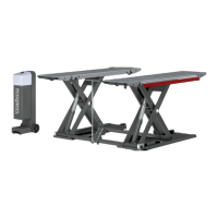
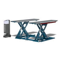
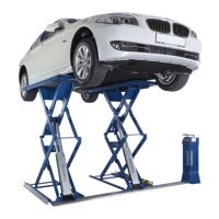
The provided document outlines the unpacking and installation process for a "Sprinter" lift, which appears to be a portable hydraulic vehicle lift.

Function Description

The Sprinter lift is designed to raise vehicles, allowing for maintenance and repair tasks. It utilizes a hydraulic system, specifically the "Twin Cross Master Hydraulic" system, which allows for flexible hose connections without affecting operation. The lift is portable, featuring wheels for easy relocation within a workspace.

Important Technical Specifications

  • Power Requirements: The unit requires a 208/230 volt, 20 amp circuit. It's crucial to note that plugging it into outlets with higher amperage breakers (e.g., 30, 40, or 50 amp) designed for welders or compressors will not protect the lift's wiring. The power lead wires are Blue, Brown (hot leads), and Yellow/Green (ground).
  • Hydraulic Fluid: It requires 2 gallons of AW32 Hydraulic Fluid. The manual explicitly states "DO NOT USE TRANSMISSION FLUID." The fluid level on the dipstick should be ignored; simply add 2 gallons.
  • Dimensions and Weight (Shipping Box): The shipping box measures 83" X 63" X 18" and weighs 1,100 Pounds.
  • Portability: The lift is equipped with a front swivel wheel and rear wheels for mobility. The rear wheels are initially stored under the platform on the lift scissor mechanism and need to be attached for portability.
  • Lifting Blocks: The package includes four 2" white "Crushblocks," which are essential lifting blocks for the lift and should not be discarded as packing materials.
  • Hardware: The lift comes with a bag of hardware including 8 axle pins and 16 external snap rings.

Usage Features

  • Ramp Attachment: The lift includes four approach/exit ramps. Attaching these ramps involves specific steps: ensuring correct positioning with the lock release lever facing outwards, attaching snap rings, inserting pins from inside-out, sliding pins through platform openings, and attaching remaining snap rings. Ramps are released by lifting the release pin while slightly lifting the ramp end.
  • Portability Mechanism: To make the lift portable, it must be raised to a minimum height of 15 inches to attach the rear wheels. The front swivel wheel slides over a "lockdog" built into the front transverse bar. Once all three wheels are engaged by lowering the lift fully, it can be pulled to the desired location.
  • Control Unit: The control unit, which houses the up/down switches, can be placed on top of the platforms for easy access during relocation or disconnected from the hoses and moved separately.
  • Tow Bar: A tow bar is included for moving the lift, and a tow bar hanger is provided for convenient storage.
  • Crushblocks: The 2" white "Crushblocks" are specifically for lifting and are an integral part of the lift's operation, not just packing material.

Maintenance Features

  • Hydraulic Fluid: Regular checking and replenishment of AW32 Hydraulic Fluid are implied, although a specific maintenance schedule is not detailed in the provided text. The initial fill requires 2 gallons.
  • Hose Connections: The Quick Connect hydraulic hoses from the lift connect to the control stations. The "Twin Cross Master Hydraulic" system allows for flexible connection, meaning it doesn't matter which hose connects to which outlet.
  • Cleaning: While not explicitly stated as a maintenance feature, the process of unpacking and setting up suggests that keeping the components clean and free of debris would be beneficial for longevity.
  • Storage: The tow bar hanger allows for organized storage of the tow bar, preventing it from being misplaced or damaged.

Unpacking and Installation Process

The manual provides a detailed step-by-step guide for unpacking and installing the Sprinter lift:

  1. Preparation: Gather necessary tools (not provided): side cutters, utility knife, hammer, 3mm Allen wrench, Phillips and straight screwdrivers, snap ring pliers, 220v plug (not supplied), 2 gallons AW32 Hydraulic Fluid, and a board for prying.
  2. Positioning the Box: It's recommended to have the trucker position the box with the wide side across the driveway/parking lot for easier removal of the lift.
  3. Crate Disassembly: Cut the bands and remove the top of the crate. Then, remove the end of the crate where the hoses are attached, being careful not to damage the hoses with the hammer.
  4. Component Identification: Identify all components, including the four 2" white "Crushblocks" (lifting blocks), four approach/exit ramps, front swivel wheel, tow bar, tow bar hanger, bag of hardware (axle pins, snap rings), owner's manual, and rear wheels (mounted under the platform).
  5. Removing the Lift from Crate: Use the board to pry the lift off the crate. Once the front torsion bar clears the crate, attach the front swivel wheel to help "rotate" the lift onto the ground.
  6. Control Station Setup: Set up the control station box with its wheels down, remove packing material, and roll it out.
  7. Control Unit Cover: Remove the top cover of the control unit using a 3mm Allen wrench, being careful not to drop it and pull wires from the switches.
  8. Power Lead: Feed the main power lead down the back of the control unit and out the bottom.
  9. Plug Attachment: Attach the appropriate 208/230 volt, 20 amp plug to the power lead.
  10. Hydraulic Fluid: Remove the dipstick and add 2 gallons of AW32 Hydraulic Fluid.
  11. Hydraulic Hose Connection: Attach the Quick Connect hydraulic hoses from the lift to the control stations. The connection order does not matter.
  12. Initial Lift Operation: Turn on the lift and raise it to full height.
  13. Ramp Attachment: Follow the specific steps for attaching the ramps, ensuring correct orientation and secure fastening with snap rings.
  14. Wheel Attachment for Portability: Raise the lift to at least 15 inches. Remove the rear wheels from their storage location under the platform and place them in the holes on the side of the rear scissors. Place the front swivel wheel over the "lockdog" on the front transverse bar.
  15. Engage Wheels: Lower the lift fully to engage all three wheels.
  16. Relocation: Pull the lift to the desired location. The control unit can be moved with the lift or disconnected and moved separately.
  17. Tow Bar Storage: Mount the tow bar hanger in a convenient location and store the tow bar.

The manual also includes a cautionary note about placing the lift with its long side at the edge of a driveway, implying potential instability or damage.

Nussbaum SPRINTER Specifications

General IconGeneral
BrandNussbaum
ModelSPRINTER
CategoryLifting Systems
LanguageEnglish

Related product manuals