MODEL NM100WH
Page 4
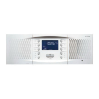
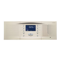
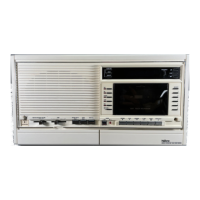
REPLACING THE ROOM STATIONS
The remote and door stations use the existing wire and station
rough-inmountingframesorboxes.Toreplacethestation,rst
remove the old station. Leave the existing remote or door station
rough-ins in place.
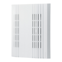
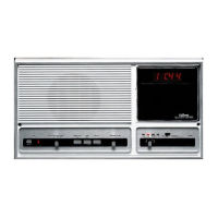
After removing the remote station verify the integrity of the wire
run. Then install the mounting plate from the NF300RWH frame.
Align the plate on the wall either vertically or horizontally so that
the screw holes line up with those on the rough-in or box. Use
a level to make sure the plate is level. There are several screw
hole locations on the mounting plate so it can attach to many
rough-in designs. Mount the plate to the wall using the screws
provided.
NM100
CONNECTION
NUTONE
IWA3 CABLE
WIRE FUNCTION
White Blue Stripe or
Outside Silver Wire
Intercom Mic
AudioInput&
Control
Red Center Wire Ground
Green Red Stripe or
Outside Copper
Wire
Speaker
Output/Monitor
Mic Input
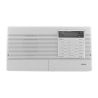
Four-wire Installations
Connect the remote station to the existing wiring using
the diagrams above. Place the remote station through the
NF300RWH plastic mounting frame. Position the frame either
vertically or horizontally depending on the remote station
Three-wire Installations
Next connect the wires to the retrot remote station. Match
the wire colors to the corresponding screw locations on the
NRS103WH or NRS104WH remote stations. Please make sure
to use only NRS103WH remote stations in a 3-wire installation
and NRS104WH remote stations in a 4-wire installation. All 6-
wire installations use the NRS200WH remote stations. Please
refertoappendixAfora diagram of which NuTone and M&S
systems map to the 3, 4 or 6-wire (requires NM200 master)
congurations.RefertothefollowingtwochartsfortheNM100
wiring diagram:
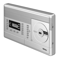
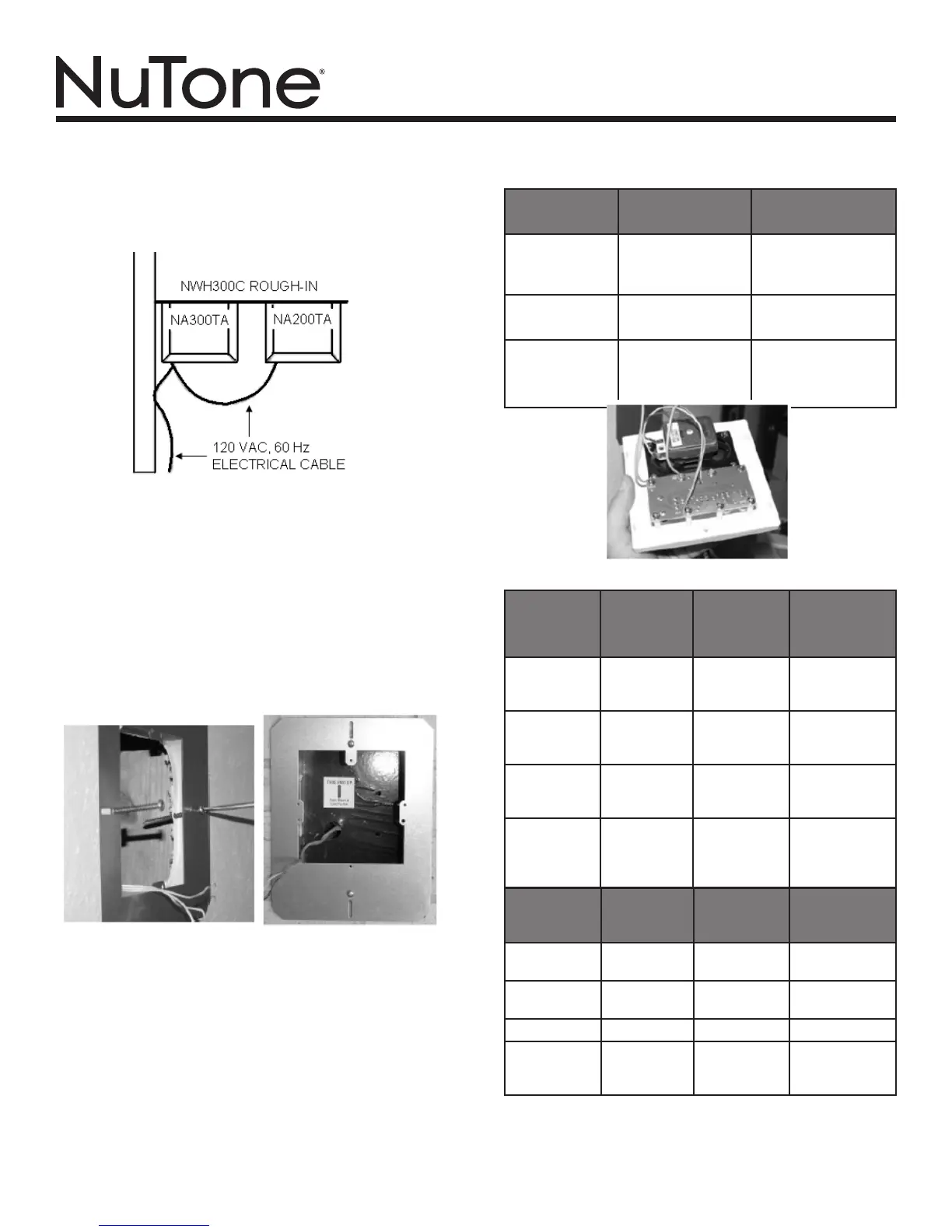
FortheNWH300CMasterStationandCDcombinationrough-in,
haveaqualiedelectricianloopapowerwirefromtheNA300TA
transformer enclosure to the NA200TA transformer enclosure
following the same procedure described previously and shown
inthenextgure.
NM100 NUTONE 4 M&S4 WIRE
FUNCTION
White Blue Stripe
Wire
Silver
Outside Gray
Wire
Intercom Mic
Audio Input
Black Gray/Copper
Wire
Next Copper
Outside Gray
Wire
Intercom
Control
Red Gray/Silver
Wire
Next Copper
Outside Gray
Wire
Ground
Green Red Stripe
Wire
Outside
Copper
Outside Red
Stripe Wire
Speaker
Output/Monitor
Mic Input
NM100 M&S
MS4XSC
CABLE
NUTONE
NW4S
CABLE
WIRE
FUNCTION
White White Red Interom Mic
Audio Input
Black Black Black Intercom
Control
Red Red Orange Ground
Green Green Yellow Speaker
Output/Monitor
Mic Input