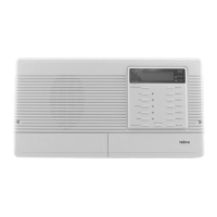
MODEL NM100WH
Page 6
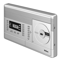
Place the jumpers you just disconnected in the 4-wire position
showninthenextgure.
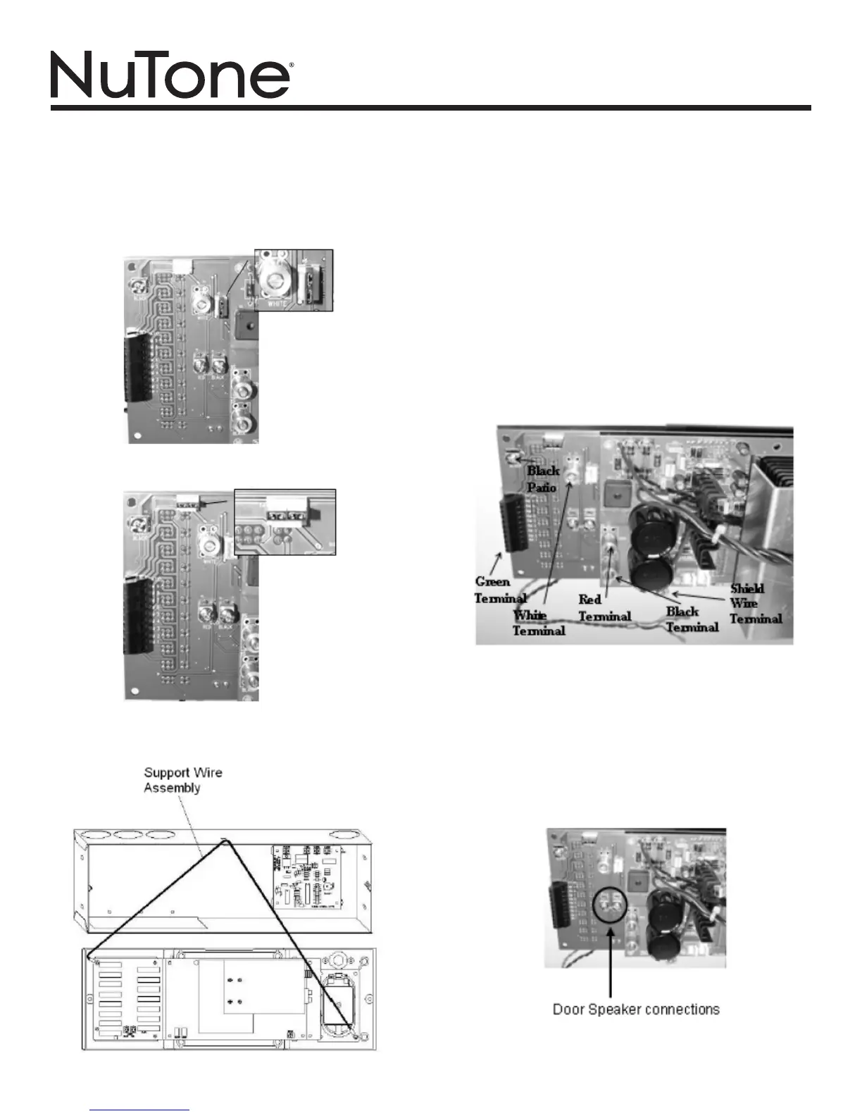
Suspend the master unit from the rough-in by looping the support
wire assembly (thick green wire) over the hook at the top of the
rough-in. Be careful not to damage the wall surface.
Plug in the modular chime plug to the 4 pin connector labeled as
CHIMEontheNM100masterunitasshowninthenextgure.
If the NM100 system has more than 9 remote stations, some
remote selector switches will control two remote stations.
Connect each Green wire (except patio/outdoor remote Green)
to a single green terminal on the master. Each numbered Green
terminal corresponds to a remote station selector switch. Note:
No more than 2 Green wires can be connected to any Green
terminal and not to exceed 15 speakers for the 4-wire or 13
speakers for the 3-wire system. This limitation does include
remote controls and volume controls but not door stations. The
station location can be marked on the inside of the door access
panel on the left side of the NM100 master.
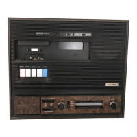
Connect the green wire(s) from the outdoor remote station(s)
to the Patio green terminal. Connect the outdoor remote Black
wire(s) to the patio Black terminal. Note: Only two outdoor remote
stations can be connected to the patio terminals. Connect the
Red wire with the other Red wires to the Red terminal. Connect
the White wire with the other White wires to the White terminal.
Refertothegureshownbelowforwireplacement.
Connect the red and black wires of the door station cables
(NW4S) to the red and black door station terminals on the
NM100 master as shown in the next gure. When using the
NW4Sshieldedwire,insulatethebarewiresusingsomeofthe
jacket material to prevent shorting to the circuit board. Connect
this wire to terminal labeled shield. Connect all orange wires
from the door stations to the common terminal on the NA3003C
or NA3008C chime module. Connect each yellow wire to a note
sleection terminal. (Do not connect more than one yellow wire
per note terminal).
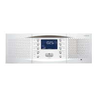
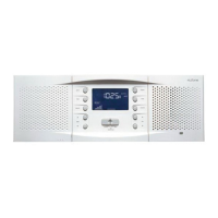
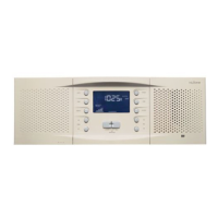
INSTALLING THE NM100
TheNM100shipsconguredfora3-wireretrotsystem.Ifyou
are replacing a 4-wire system you must change the jumper setup
on the NM100 master. The jumper change must be completed
before any cables are connected. To change the jumpers just
pullthemofftheexistingconnectionsshowninthenextgure.