OMC-183-ML Manual Page 13
3. Commissioning the OMC-183-ML
There are two output options, both use one way RS-422 serial communication. One contains the
NMEA data protocol format. The other one got the old OMC-2900 format for backwards
compatibility purposes. To execute analog input calibration and other configuration settings, there
is also a bi-directional RS-232 menu available.
To read the sensors, each unit contains four 0-5 Voltage inputs and three 0-24mA current inputs.
All these analog inputs have already been configured during the manufacturing process.
3.1. Connecting your PC / laptop to the OMC-183-ML
Since most computers don’t have a comport any more, an additional Serial to USB adapter is
needed. Install a terminal program like HyperTerminal, OMC-Terminal, Procomm+, etc. and use
the following settings for the different COM ports.
NO flow control!
3.2. Device status
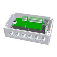
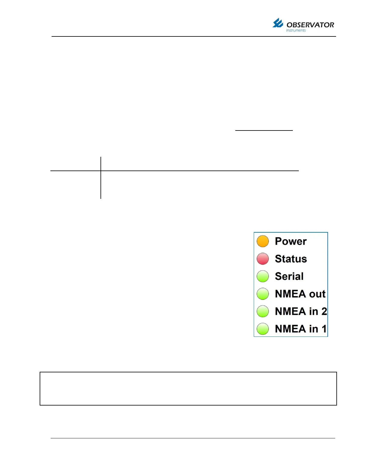
There are six LED’s on the bottom right corner of the printed circuit board,
they indicate the status of the device. After power-up the orange LED
indicates that the microcontroller is powered. The second LED is red and
indicates a bus overflow, when this LED blinks there is too much data
input to send all incoming messages as output. In this case the device
has to ignore some input messages and information might not be sent as
output and information might get lost.
The other four green LED’s indicate the status of the Serial, NMEA out,
NMEA in 2, NMEA in 1 inputs. When valid messages are received these
LED’s blink. All NMEA messages have to be compliant in order to let de
LED blink. For the serial LED a blink means that a valid RS-485, RS-
232 or other sensor message is received. For each serial sensor a
software driver is included in the device. In order to connect jet unknown
sensors an additional driver and new firmware is needed.
Default data settings
Baud rate, Data bits, Parity, stop bit
115200 (or 4800/9600), 8, N, 1
If you experience difficulties connecting with the device; Check if the LED’s are blinking, Check the
wiring of the Tx/Rx or A/B wires; Check the data settings of your COM port.
Note: The RJ-45 / Ethernet option is not active on the OMC-183-ML, theses LED’s are switched off.