Sensor Name: change this to describe the input. This can be anything you wish, such as “Indoor Temperature”
Input Mode: Select from one of the following: Voltage 0-10v, Current 4-20mA, Resistance, Pulse, Pulse-KYZ, status or
Unconfigured.
Sensor Make and Model: This entry is a space for the model number of the sensor. It is only used for reference.
Sensor Minimum Range: All Analog Sensors have min/max range values. For example, a temp sensor may have a
range of 50 to 95 degrees F. Enter the low range number here.
Sensor Maximum Range: Enter the high range value of the analog sensor here.
Pulse Multiplier: for pulse mode inputs, this option specifies the multiplier for the input.
Curve Scaling: Some sensors such as thermistors have a non-linear output. This option allows a lookup table to be
specified to convert from the input reading to an engineering unit data output. Several conversion tables (Curve Scale
Templates) are provided with the AcquiSuite. For more information refer to the Curve Scale Documentation supplement
provided on the obvius.com website.
Pulse Rate: for most units, this feature is an automatic rate field. For KWH points, the rate is KW.
Engineering Units: Enter the units of measure. ie, Degrees F, %RH, etc.
5. After saving the sensor profile, the device configuration page will be displayed again. The input values should now be
scaled correctly and the names will be updated to your new configuration. You may wish to set any alarm thresholds
required, or check the “console” check box for any data points that should be displayed on the LCD console.
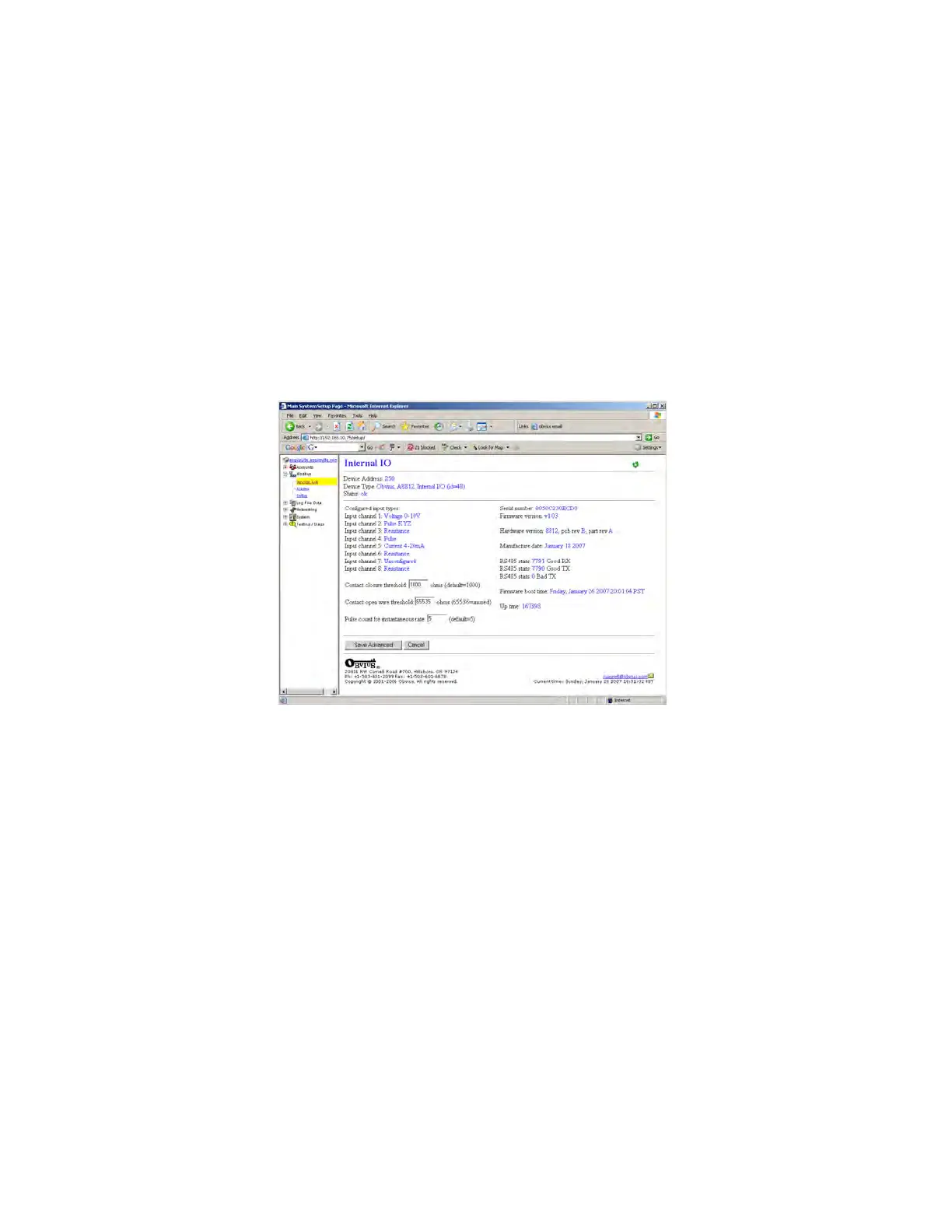
6. Click the “Advanced” button in the lower right corner of the page. For the A8812 onboard IO, there are several options.
Input types: this list shows the status of the 8 analog inputs, either 0-10V, 4-20mA, resistance, pulse, status, etc.
The Contact Closure Threshold allows you to set a maximum resistance to be counted as a “closed” contact. This is
helpful when using intrinsic barrier devices.
The Contact Open Threshold can be used in conjunction with a 20K resistor in parallel with the contact closure. When
the contact is open, the AcquiSuite will read 20K, when closed, it will read <100ohms. If the wire is broken, the reading
will go above 20k ohms, and will cause an alarm condition.
The Pulse count for instantaneous rate value specifies the number of puses to use to calculate the instantaneous rate,
min, and max fields in pulse mode.
7. After returning to the device configuration page, click “Save” at the bottom of the page to return to the device display
page.
The internal io device 250 is also available to the Modbus TCP gateway feature. External systems such as computer
software or PLC may send a Modbus TCP query to the AcquiSuite using Modbus address 250. The internal io device will
respond with Modbus registers that represent all of the features seen in the AcquiSuite configuration pages. Complete
documentation of the Internal IO device 250 Modbus registers is available online on the website obvius.com in the A8812
overview section.
Page 19 A8812 AcquiSuite – Data Acquisition Server
Shop for Power Metering products online at:
1.800.561.8187
www.PowerMeterStore.ca