MNL-1012 Rev A
14
Electrical Pinout
The Flame features a 40-pin Accessory Connector, located on the front of the unit.
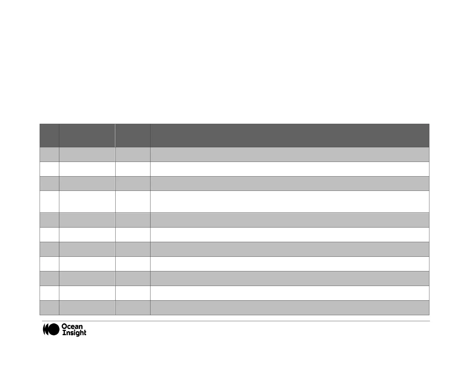
DD4 Accessory Connector Pinout Description
When facing the 40-pin Accessory Connector on the front of the vertical wall of the Flame, pin number 1 is on the right.
Listed below is the pin description for the Flame Accessory Connector. The Flame will include a JAE DD4 receptacle, part number
DD4RA40JA1. Most accessories that plug into the Flame will include a JAE DD4 plug, part number DD4PA40MA1. There is also a
vertical connector, JAE part number DD4BA40WA1.
TTL output signal used to pulse a strobe that is divided down from the Master Clock signal.
TTL output pulse used as a strobe signal, which has a programmable delay relative to the beginning of
the spectrometer integration period.
A TTL signal that is driven Active HIGH when the Lamp Enable command is sent to the Flame.
General Purpose Software Programmable Digital Inputs/Output*
General Purpose Software Programmable Digital Inputs/Output*
General Purpose Software Programmable Digital Inputs/Output*
General Purpose Software Programmable Digital Inputs/Output*
General Purpose Software Programmable Digital Inputs/Output*
General Purpose Software Programmable Digital Inputs/Output*