Installation
Page 43
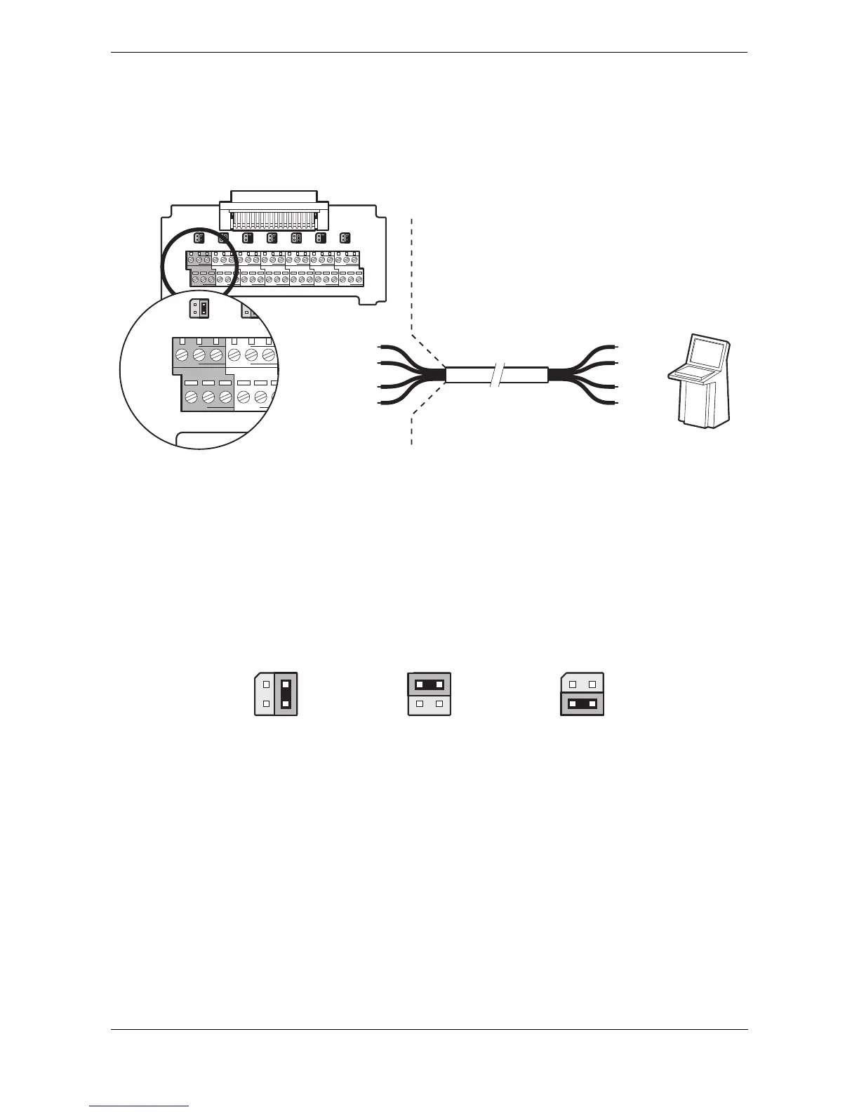
An example of connection to external display equipment is provided in Figure 43, and connections to other
equipment and sensors follow the same scheme. To determine the ‘A’ and ‘B’ signal lines on external
equipment use a digital volt meter to measure the signal line voltage referenced to ground. If the voltmeter
shows a negative voltage the ‘A’ signal line is being measured, a positive voltage indicates the ‘B’ signal line.
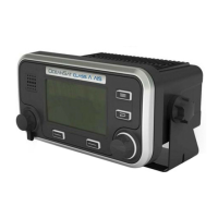
Figure 43 Example connection to external display equipment
The junction box provides jumpers to select alternative line termination configurations for data input
connections from remote equipment. The line termination options are:
● None - no line termination, suitable for short cable runs less than 10m (as supplied).
● R - 120 Ohm line termination, suitable for longer cable runs greater than 10m.
● RC - AC 120 Ohm / 1uF termination. Not used.
Select the appropriate line termination option for each data input connection using the jumper adjacent to the data
input connection in the junction box. The jumper positions for each termination option are shown in
Figure 44.
Figure 44 Line termination options