Installation
Page 44
Along with data port connections the junction box also provides connections to the AIS transceiver alarm relay
contacts. The common and normally open alarm contacts are duplicates of the alarm relay connections
available at the power connector (see
Table 5) whilst the normally closed contact is only provided at the junction
box. The alarm relay connections are described in Table 5. Use the alarm connections appropriate to the
vessels alarm system.
Table 5 Alarm relay connections
4.4.5 Power and alarm connections
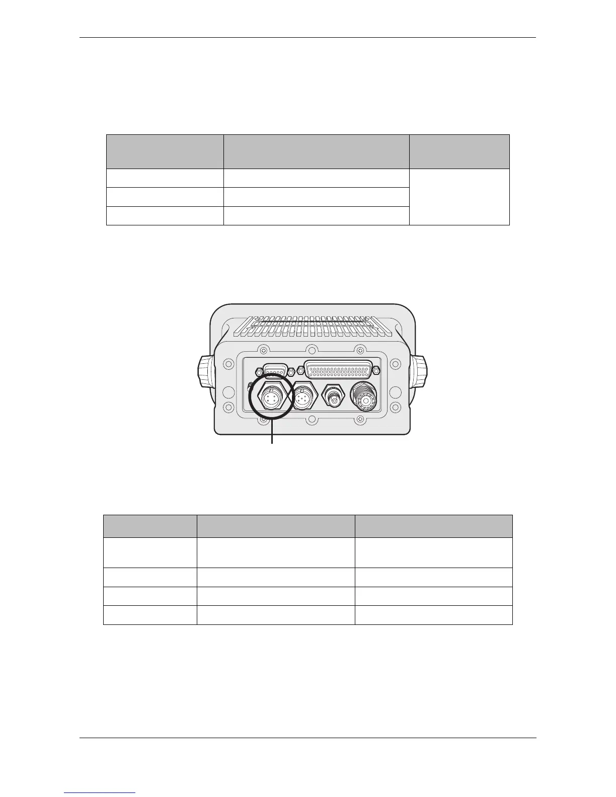
Power is connected to the transceiver via the supplied four way power and alarm cable as shown in Figure 45.
Figure 45 Power connection
The power and alarm cable contains four wires which should be connected according to Table 6.
Table 6 Power supply connections
*Connection to an emergency power source is an IMO requirement for SOLAS vessels.
The power supply current ratings and recommended fusing or circuit breaker currents are as follows:
● A 12VDC supply should be able to provide 4.0A and be fused at 8.0A.
● A 24VDC supply should be able to provide 2.0A and should be fused at 4.0A.
Junction box alarm
connection
Function Contact rating
COM Alarm relay common connection
220V or 2A or 60W
maximum
NC Alarm relay normally closed connection
NO Alarm relay normally open connection
Wire colour Function Connect to
Brown Power supply + 12V or 24V DC power supply from
ships emergency power source*
Black Power supply - Power supply ground
White Alarm relay normally open contact Bridge alarm system
Blue Alarm relay common contact Bridge alarm system