Replacement
Follow these steps to replace the Power/Motor Relay PCB:
1. Turn the Workstation off and disconnect its power plug from the AC outlet.
2. Remove the Front Cover by lifting the rubber gasket that surrounds the Vertical Column and removing two screws from each
side.
3. Disconnect all wiring from the Power/Motor Relay PCB.
4. Remove four screws that secure the Power/Motor Relay PCB to the chassis.
5. Install replacement Power/Motor Relay PCB.
6. Reassemble C-Arm and check it for proper operation.
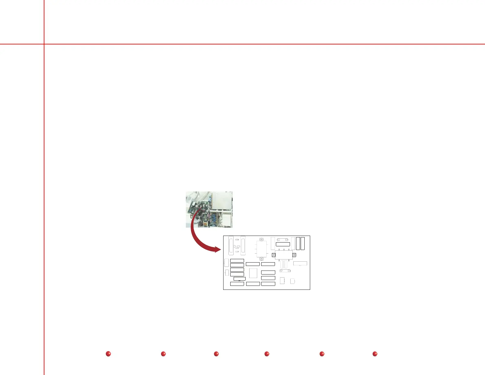
Power Signal Interface PCB
The Power/Signal Interface PCB is located under the Left Side Cover as shown next. For detailed access information, refer to
the Overview section of this manual.
RT2
RT1
P11
TP1
TP3
TP6
TP5
LF2
LF1
CR1
P6
F5
F3
F12
F6
J1
F2
F10
F7
F11
F8
F9
F1
F13
F14
F15
F16
P6
P7
TP4
P10
P4
P8
P3
P5
TP2
View from
left-hand side of
generator with
cover removed.
DS1
RT3
R1
CR2
J1
P3
Power/Signal Interface PCB
76
Service
Periodic Maintenance
Contents
Schematics
Illustrated Parts
Installation
 Loading...


