7
Operating Instructions and Parts Manual 24664
4/18
2018 OEMTOOLS
™
ROTARY TOOL
PARTS DIAGRAM
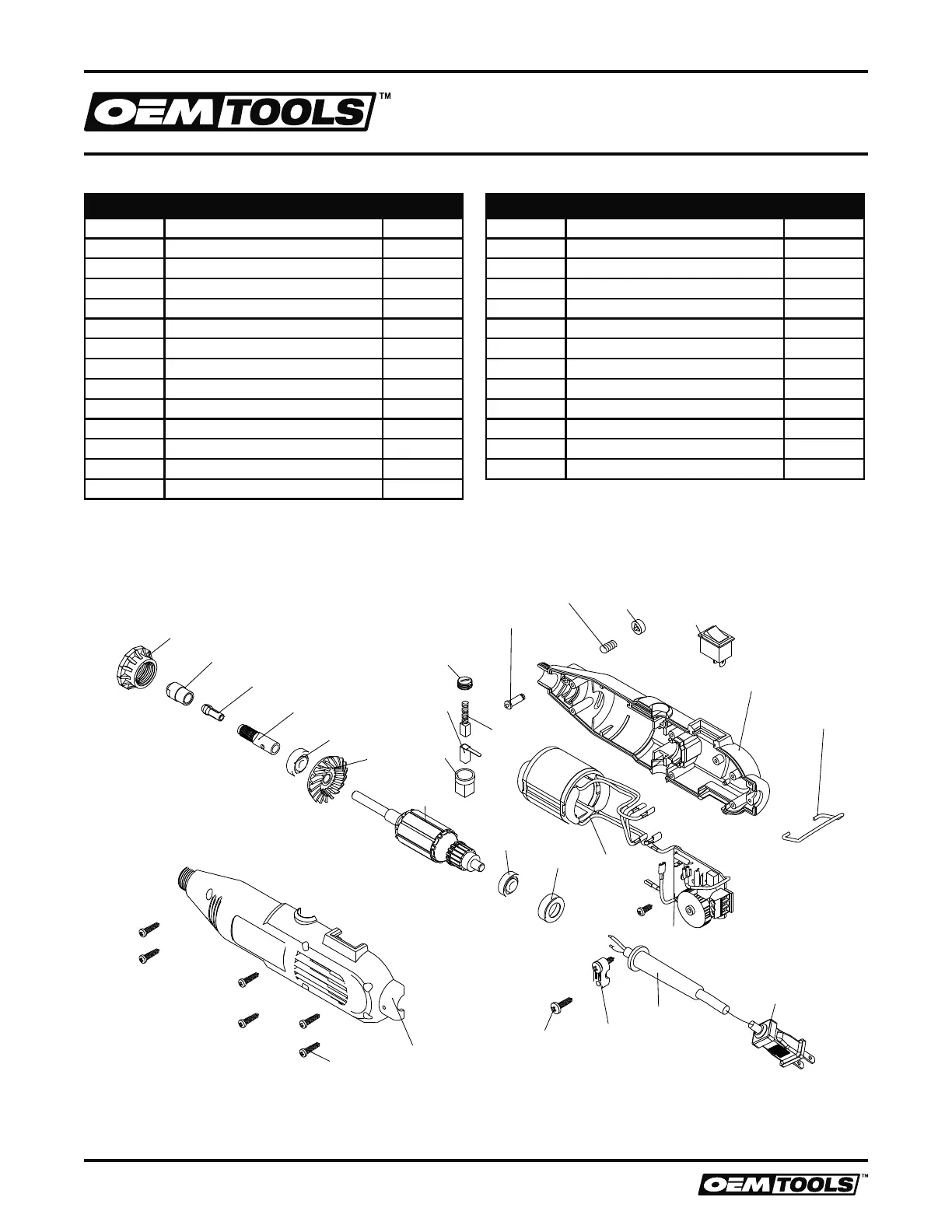
PARTS LIST
NOTE:
Not all components of the Rotary Tool are replacement items, but are illustrated as a convenient reference for location
and position in the assembly sequence.
Item # Description Quantity
1 Screw 6
2 Left Enclosure 1
3 Screw 2
4 Cord Clamp 1
5 Cord Guard 1
6 Power Plug 1
7 Variable Speed PCB 1
8 Stator 1
9 Bearing Sleeve 1
10 Bearing 606-2Z 1
11 Carbon Brush 2
12 Carbon Brush Cap 2
13 Brush Holder 2
14 Brush Holder Support 2
Item # Description Quantity
15 Rotor 1
16 Fan 1
17 Bearing 626-2Z 1
18 Output Shaft 1
19 Collet 1
20 Collet Nut 1
21 Head Nut 1
22 Shaft Lock Spring 1
23 Shaft Locking Pin 1
24 Shaft Lock Button 1
25 Switch 1
26 Right Enclosure 1
27 Hook 1
11
6
12
1
2
3
4
5
17
21
20
19
18
16
10
14
13
15
9
8
22
23
24
7
25
26
27