M
Michael BergAug 16, 2025
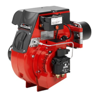
What to do if my Oilon RP-130 H has a motor failure?
- KKristy SandovalAug 16, 2025
If your Oilon Burner experiences motor failure, several issues could be the cause. It could be due to a break in the main circuit, in which case you should repair the break. Other potential causes include a triggered motor overload relay (check the relay trigger level, reset, or change it), a triggered fuse (reset or change the fuse), a faulty motor contactor (change the motor contactor), or a faulty motor (change the motor). It might also be due to a break in the motor control circuit (repair the break), a faulty control unit (change the control unit), incorrect settings of the air-dampers servomotor camswitches (fix the setting of camswitches), or a faulty air-dampers servomotor (change servomotor).