15
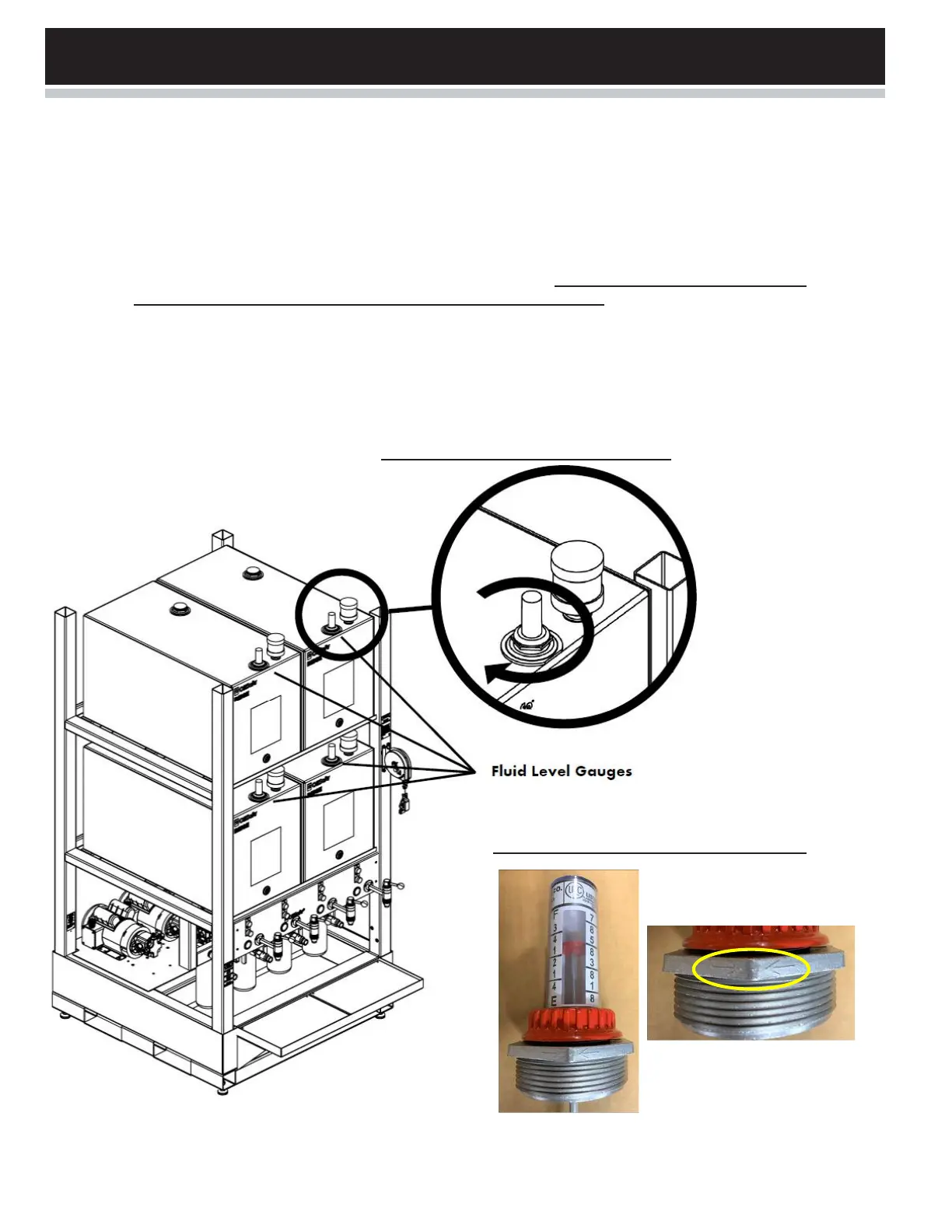
STEP 8. Installing the Fluid Level Gauges See Figure 8a and Figure 8b for details.
a. Unscrew and remove the red plastic locking nut from level gauge.
b. Remove the clear calibration tube.
c. Gently pull up the red indicator disc.
d. Carefully insert the float assembly into the tank.
e. Screw the aluminum bushing into the tank port until tight and ensure the arrows on the flat side
of the hex bushing are pointing toward the back wall of the tank.
f. Gently raise & lower red indicator disc to ensure the float mechanism is free andclear inside the
tank.
g. Reinstall the clear calibration tube.
h. Fasten the red locking nut (as illustrated).
FIGURE 8a: Install Fluid Level Gauges
FIGURE 8b: Level gauge alignment arrows