B A -- +
Blue Red Brown Yellow
p. 3
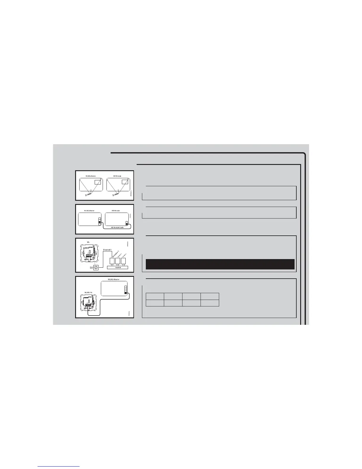
We recommend the preparation of an area schedule chart on the backside of the user manual before
commencing the installation. This identifies piping circuits to specific rooms and enables the correct
allocation of a channel number in the WLM system.
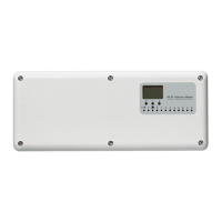
Mount the Master and AO modules in the correct way on the wall in accordance with electrical
regulations.
Connect the AO-module, using the special cable included in the box.
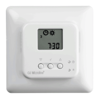
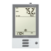
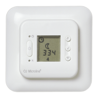
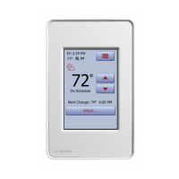
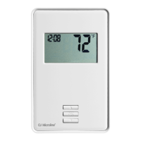
Mount the Room sensors/controllers in the rooms, and set the channel switches to correspond with
the number of the actuator controlling that room.
For hardwired Room sensors/controllers now connect the 2-wire bus to the master or the AO module,
maintaining continuity of positive + and negative - connections.
For wireless Room sensors/controllers now insert the batteries.
If the Room sensors/controllers are of wireless type connect the receiver (WLRC-19) using the special
cable enclosed with the receiver.
NB: For Room sensors with floor temperature limiting sensors, please refer to separate instructions
included with Room sensors/controllers.
QUICK INSTALLATION GUIDE
1
2
4
3
QUICKGUIDES
QUICKGUIDES