7. Connection Diagram
Oki Data CONFIDENTIAL
44983601TH Rev.1
7-8 /
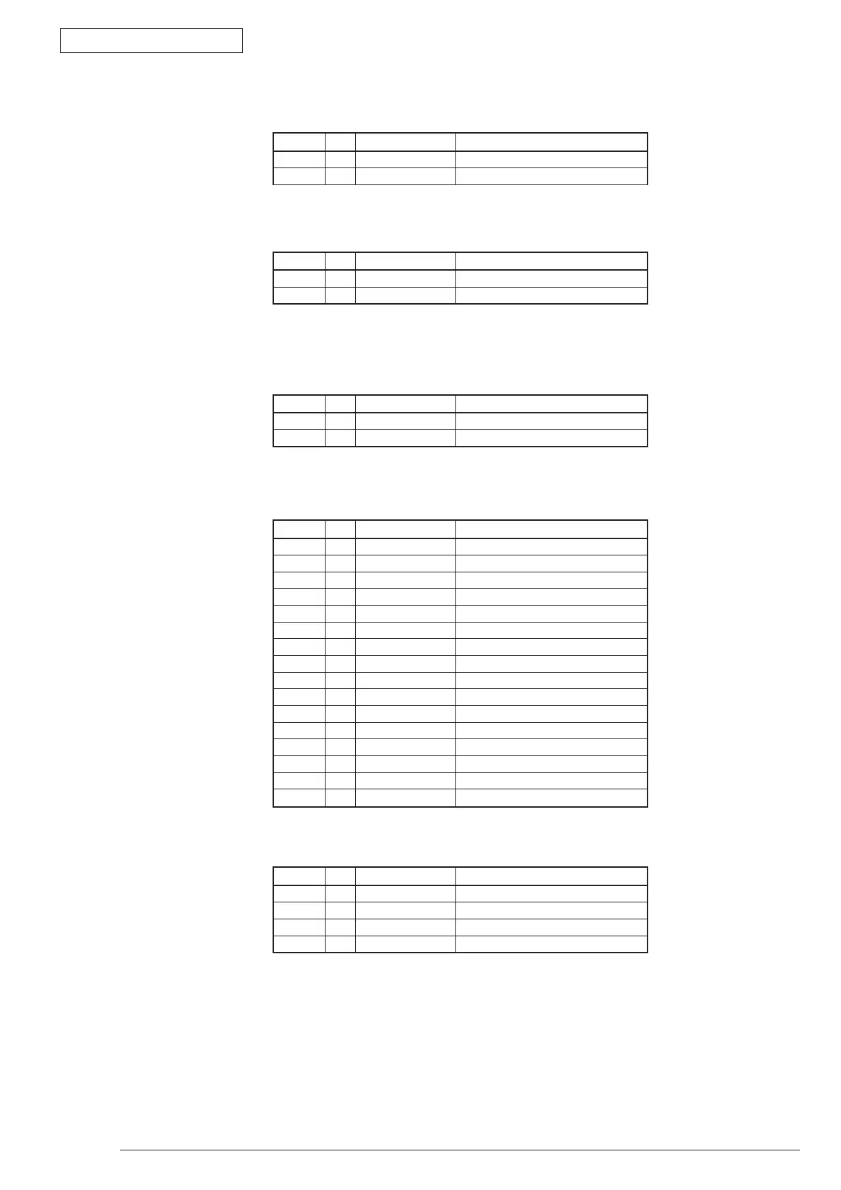
• RCLTConnectorPinAllocation
(Connection to the Regist Clutch)
• HCLTConnectorPinAllocation
(Connection to Hopping clutch)
• MCLTConnectorPinAllocation
(Connection to the Multi-feeder Clutch)
• LCDPNLConnectorPinAllocation
(ConnectiontotheOperatorPanel)
ForB411dnonlyusePinNo.1~11.
PinNo. I/O Signal Function
1 O +24V ClutchDrivePower
2 C REGIST AnalogGround
PinNo. I/O Signal Function
1 O +24V ClutchDrivePower
2 C HOPPING AnalogGround
PinNo. I/O Signal Function
1 O +24V ClutchDrivePower
2 C MPT AnalogGround
PinNo. I/O Signal Function
1 O LCD_RS RegisterSelection
2 O LCD_CSB Register Clear
3 O LED2 LEDON
4 O LCD_CLK SerialClock
5 I CYRI LCD type distinction
6 O LCD_DO SerialData
7 O +3.3VLCD LogicCircuitPowerSupply
8 O LCD_RST LCD Reset
9 O LED1 LEDON
10 I SW6 Switch6
11 C GNDLCD Logic Ground
12 I SW5 Switch5
13 I SW4 Switch4
14 I SW3 Switch3
15 I SW2 Switch2
16 I SW1 Switch1
• TONERConnectorPinAllocation
(ConnectiontotheTonerSensor)
PinNo. I/O Signal Function
1 O +5V LogicCircuitPowerSupply
2 I TONER TonerSensor
3 C GND Logic Ground
4 - NC Notused