7. Connection Diagram
Oki Data CONFIDENTIAL
44983601TH Rev.1
7-9 /
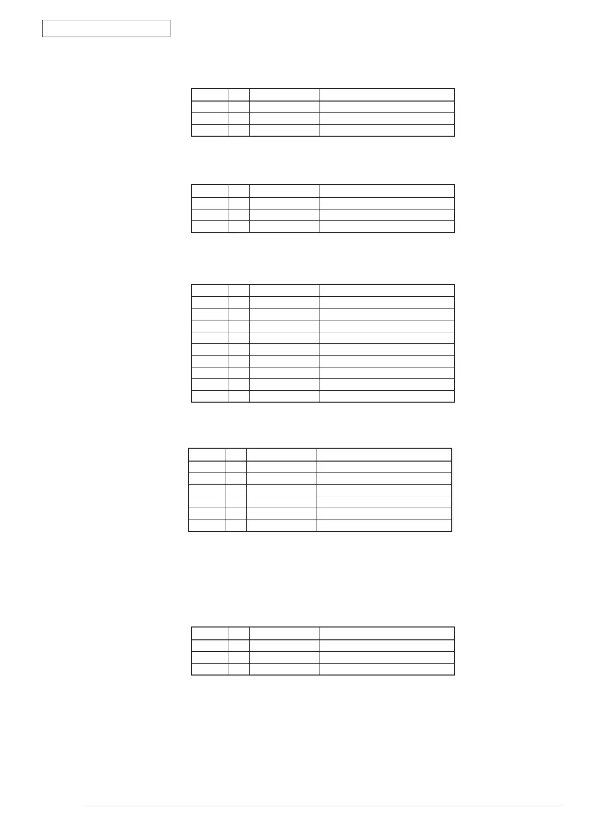
• RCOConnectorPinAllocation
(ConnectiontothePhotointerrupter)
• EXITConnectorPinAllocation
(ConnectiontothePhotointerrupter)
• DMConnectorPinAllocation
(Connection to the DC Motor)
PinNo. I/O Signal Function
1 O +5V LogicCircuitPowerSupply
2 I RCOPN-N Rear Cover open
3 C GND Logic Ground
PinNo. I/O Signal Function
1 O +5V LogicCircuitPowerSupply
2 I EXIT-N Detection of the media output
3 C GND Logic Ground
PinNo. I/O Signal Function
1 O +24VIC LogicCircuitPowerSupply
2 O DMON-N Motor-ONsignal
3 I DMLOCK-P MotorLockdetection
4 O DMCLK-P MotorClock
5 O GAIN-P Motor Gain Chang
6 O +24V MotorDrivePower
7 O +24V MotorDrivePower
8 C 0VP AnalogGround
9 C GND Logic Ground
• IN_WRConnectorPinAllocation
(ConnectiontothePhotointerrupter)
• PWFAN1ConnectorPinAllocation
(ConnectiontotheMotor-Fan(Power))
PinNo. I/O Signal Function
1 O +5V LogicCircuitPowerSupply
2 I IN INSensor
3 C GND Logic Ground
4 O +5V LogicCircuitPowerSupply
5 I WR WRSensor
6 C GND Logic Ground
PinNo. I/O Signal Function
1 O FANPOW FANDrivePower
2 C FANGND AnalogGround
3 I FANALM FANAlarmDetection